Don't see a d206c?The two d205c's(assuming one for each side) measure fine in circuit in diode check in one direction(.06).
Should we pull and check and or is the 206 supposed to be near the same area?I see it nowhere.
Should we pull and check and or is the 206 supposed to be near the same area?I see it nowhere.
Sorry I meant .6...There both 205 in this amp?.Anyhow,with red probe on anode/black on cathode its 4.5k after it settles down.Probes reversed,about 5.6 k after many seconds when it settles down.Both still in circuit.
That sounds OK. The difference is probably in the way your meter determines the resistance.
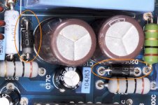
Is the other 10 ohm resistor within tolerance?
What is the DC voltage across both 10 ohm resistors with the amp on?
Is the other 10 ohm resistor within tolerance?
What is the DC voltage across both 10 ohm resistors with the amp on?
Both within tolerance.Burnt one has 6+vdc across and other has +1vdc across.Seems like a problem lol.
Perry,I feel like a total dumbass now.You just nailed the problem(really appreciate it)
The original cap was a 153h100.I had a 104j100 in that spot.I just swapped what I'm assuming is channel a from channel b and the resistor heat transferred to the other 10R resistor.I did order the right ones but don't have them yet.Can you explain why a fraction of a NF made such a chance?
I've over the years on various things used higher UF caps with no problems.I do refrigeration and change caps all the time without problems.Of coarse this is commercial related and not electronics based.If its to much to ask I can try to read about it on the net.
Thanks again
The increased capacitance allowed more of the carrier waveform to pass through the capacitor and resistor. It's like increasing the value of the capacitor for a high-pass crossover for a tweeter. The increased capacitance would allow the tweeter to receive more power and possibly blow it.
Sorry but I have a couple more questions..sorry
What's the potentiometer for (vr12) I believe I may have have came a crossed it in the tutorial.A lot of stuff to try to remember.
Also, this thing draws about 1.5 amps.Also from rca ground to speaker ground is 32 +vdc?
And 166K from rca ground shield to amp ground lug? Perhaps another issue or something I don't understand?
VR12 is the DC offset adjustment.
The speaker terminals are at 1/2 of rail (both positive and negative).
The input isn't referenced to any grounds in the amp. It's essentially a balanced input.
The speaker terminals are at 1/2 of rail (both positive and negative).
The input isn't referenced to any grounds in the amp. It's essentially a balanced input.
I understand hip4080 amps have half rail voltage on speaker terminals.Just wasn't sure about the rca and all 4 terminals having output signal.
Awesome.This is my first time playing with a hip4080 design.Thanks for the help.I'm gonna put the hammer to it and see what happens.
I'm so sorry for all the questions.Think there still may be a problem.The original burnt resistor still gets fairly hot.Just take a minute longer now.The other 10R stays room temp.
There's some static on the output with a speaker connected.The output is ever so slightly distorted.
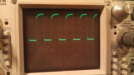
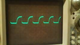
Here's some pics of the low/high side outputs from the channel with burnt resistor.Actually both channels look the same.No input signal on these photos.
There's some static on the output with a speaker connected.The output is ever so slightly distorted.
Here's some pics of the low/high side outputs from the channel with burnt resistor.Actually both channels look the same.No input signal on these photos.
Current draw of less than 2 amps is OK.
The waveforms look OK.
What are you using for an input signal?
The waveforms look OK.
What are you using for an input signal?
- Status
- Not open for further replies.
- Home
- General Interest
- Car Audio
- Hifonics Brutus 1500 hip 4080 issue