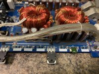
This amp uses 12 IRFP064N’S for the power supply fets .
Something doesn’t look right here unless I’m over thinking this .
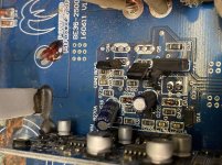
There is a spot for 4 driver transistors but there only 2 in this amp .
Is there supposed to be 4 or only 2 ?
Replaced the driver transistors (C3228) with BD139 .
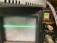
Once I load the drive circuit all drive signal disappears .
Something doesn’t look right here unless I’m over thinking this .
There is a spot for 4 driver transistors but there only 2 in this amp .
Is there supposed to be 4 or only 2 ?
Replaced the driver transistors (C3228) with BD139 .
Once I load the drive circuit all drive signal disappears .
Attachments
Last edited:
Drive circuits typically have either a diode and PNP transistor or an emitter-follower pair. I don't see any diodes.
The collector of the PNP transistors go to ground. Confirm that the center pad is ground and if so, use a BD140.
The collector of the PNP transistors go to ground. Confirm that the center pad is ground and if so, use a BD140.
The center pins go to the Battery plus not the negative terminal .
The 2 spots on the board that are not populated are where the pnp drivers would go .
So I’m wondering if the got hot and desoldered themselves and someone took them from the board
The 2 spots on the board that are not populated are where the pnp drivers would go .
So I’m wondering if the got hot and desoldered themselves and someone took them from the board
Attachments
Last edited:
I used BD139 for the C3228’s .
You said you didn’t see any diodes so use bd140 of the center pins go to the ground terminal of the amp .
The center pins do not go to the ground terminal of the amp .
The empty locations still remain empty at this point . The empty locations venter pin goes to ground
So do I leave the empty locations empty or pit 140’s in there ?
With regards to the diodes mentioned, I was simply telling you that there are two possible options and your amp used the second EF pair option.
Are the center connections to ground burned open?
Are the center connections to ground burned open?
Let’s try to make this less confusing for both of us .Q7 and Q7A were populated when I revived the amp .
Q7 and Q7A center pin goes to the fets drain (center leg)
Q8 and Q8A were not populated when I revived the amp there center pins go to the ground terminal of the amp . There connection to the ground terminal was never burnt open .
The only thing I found burnt open was a 0 ohm resistor labeled RGND was burnt open which connects from ground terminal of the amp to the rca shield ground of the rca jacks .
So my question is I should leave the 2 bd139’s in locations Q7,Q7a and populate Q8,Q8A with BD140’s correct ?
Last edited:
Post #2:
The collector of the PNP transistors go to ground. Confirm that the center pad is ground and if so, use a BD140.
^^ Why didn't this clear things up?
The center leg of the NPN drivers do not go to the center leg of the drains. They go to B+. The drains are connected to B+ through the transformer.
The collector of the PNP transistors go to ground. Confirm that the center pad is ground and if so, use a BD140.
^^ Why didn't this clear things up?
The center leg of the NPN drivers do not go to the center leg of the drains. They go to B+. The drains are connected to B+ through the transformer.

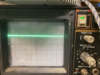
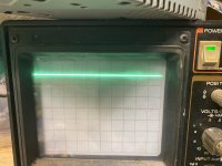
Set your scope to 5v/div and touch it to the positive terminals of your 12v PS. Post a photo of scope display with the probe on that terminal. Also post the DC on your power supply voltage (read with multimeter).
- Home
- General Interest
- Car Audio
- Hifonics BE35-2500.1D