The ripple eater (any ripple eater) will remove LF mains rectification noise off the supply rails. Under no load, a typical amp will have 200-500mV 100/120 Hz sawtooth ripple and that goes up with load. Ripple eaters effectively shift the ripple noise down in frequency so that the changes on the rails go from 100/120 Hz sawtooth to <1 Hz (ripple eater RC time constant specific). You always loose a volt or two across the RE and under load, the DC output will be at the trough of the ripple voltage plus some further DC drop across the series pass transistor.
It will not fix bad wiring resulting in earth loop or common impedance coupling noise. It will improve the PSRR of a system by 30-40 dB.
Increasing the cap filter bank is another way of doing it, but that is gets expensive if you want to reduce the ripple by 30-40 dB and you then have concomitantly higher charging currents to deal with.
As in all things, there is a balance to be had.
🙂
No - I'd just stay with the original board. A good upgrade is to replace the MJE15032/22 pass devices with TO3P devices like the NJW3281/1302 and mount then off board on the amplifier heatsinks which is also what I've done on my kx2-Amp. Quite a few builders have done this - it will allow full power testing of the kx2/sx amp into 2 Ohm loads in class A.This micro has few components more than the original sx/kx amp ripple eater?? (which i have in the works now)
Should i try to add R1, R2, R9, R10, D5, D6 and C3, C4 to older board, if even possible?
A builder (Tony from Australia) has pointed out the BOM and the PCB silkscreen and circuit are not aligned for R1 and R2. R1 and R2 must be 10k and not 1k. The BOM is correct.
Thanks for this addition to your amplifiers Bonsai. I cannot see the dimensions for the MRE pcb. Can someone please post the overall footprint of the board with transistors projecting as I am designing a new case for mine and haven't ordered the actual boards yet.
Oops! I should have said overall footprint dimensions.Thanks for this addition to your amplifiers Bonsai. I cannot see the dimensions for the MRE pcb. Can someone please post the overall footprint of the board with transistors projecting as I am designing a new case for mine and haven't ordered the actual boards yet.

@Bonsai
Hifisonix Micro Ripple Eater PDF
On slides 5 and 6, should the sections to the left of the red letter ‘A’ be labeled ‘Ground’ or Zero volts instead of V+/V- ?
And if you can update the document with dimensions that would be great!
Best,
Anand.
Hifisonix Micro Ripple Eater PDF
On slides 5 and 6, should the sections to the left of the red letter ‘A’ be labeled ‘Ground’ or Zero volts instead of V+/V- ?
And if you can update the document with dimensions that would be great!
Best,
Anand.
Last edited:
Hello Bonsai
I've seen a lot of introductions mentioning that capacitor multipliers are not recommended for Class AB amplifiers.
I'm curious, is there really no problem with capacitor multipliers for Class AB amplifiers with drastic changes in current?
I've seen a lot of introductions mentioning that capacitor multipliers are not recommended for Class AB amplifiers.
I'm curious, is there really no problem with capacitor multipliers for Class AB amplifiers with drastic changes in current?
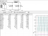
I've never seen this. You will lose a volt of two in output voltage swing, but that is normally not a problem if the amplifier is powered off sufficiently high voltage rails. What you can do is place the ripple eater after the power output stage but before the small signal stages - I did this in my e-Amp from 2012 ( http://hifisonix.com/ovation-e-amp/ ). The scope shot below is the waveform across D3. The attenuation of supply rail ripple was about 40 dB at LF and >50 dB at HF - top trace was the cathode and bottom trace the anode.


Last edited:
Note in the e-Amp, the current draw from the cap multiplier stage was about 30mA IIRC so that’s why I just used an emitter follower. If the current draw is high, you will need to use a Darlington which is what I use on the MRE.
And it weighs 10 kg and occupies about 100 cubic inches. It also doesn’t have the bandwidth of a cap multiplier (100’s of kHz).
Only 5kg, not 10, the volume is less than one cubic
decimetre, the world is metric, not imperial 🙂
Simplicity is the most important criterion in audio,
too many parts make too many problems 🙂
decimetre, the world is metric, not imperial 🙂
Simplicity is the most important criterion in audio,
too many parts make too many problems 🙂
You will have a hard time convincing me any most others that a CLC filter is a better option for filtering the supply rails in a solid state amp all things considered. For a tube amp with high voltage rails and low current draw they may make sense but not in a solid state amp.
Separately, I am of the opinion, as are the experts that study this stuff, that the world is round and about 7900 miles in diameter.
Separately, I am of the opinion, as are the experts that study this stuff, that the world is round and about 7900 miles in diameter.
Yes, correct.
Usually, I'm using Hammond inductors for my projects.
As my drivers are sensitive enough, I don't need a lot of power.
About 5-15 watts, SE, valves or solid state, without any feedback.
My last project is SE 2SK79/2x ECX10N20, supplied by 24VAC. The
CLC is 22mF/28mH(3A)/22mF with only 5mV ripple.
Usually, I'm using Hammond inductors for my projects.
As my drivers are sensitive enough, I don't need a lot of power.
About 5-15 watts, SE, valves or solid state, without any feedback.
My last project is SE 2SK79/2x ECX10N20, supplied by 24VAC. The
CLC is 22mF/28mH(3A)/22mF with only 5mV ripple.
Last edited:
Anand,@Bonsai
Hifisonix Micro Ripple Eater PDF
On slides 5 and 6, should the sections to the left of the red letter ‘A’ be labeled ‘Ground’ or Zero volts instead of V+/V- ?
And if you can update the document with dimensions that would be great!
Best,
Anand.
updated 🙂
- Home
- Amplifiers
- Power Supplies
- Hifisonix Micro Ripple Eater