So who else is into “HiFi” AM on the HF HAM bands then? 😀
I’m currently building up my HAM shack and converting a huge 2kW carrier 500kHz MCW transmitter for legal transmission on the 160m band.
The transmitter uses four 4CX1000A’s in the final (parallel push-pull) in class AB1 for linear amplification, low-level modulation.
A few simple mods to the pre driver and driver stages is required for operation at 1.8MHz and the final will be converted by disconnecting the 500kHz plate output transformer and installing a 1.8MHz tank circuit / pi tuner directly above the 4CX1000A anodes (There is plenty of room in the cabinet).
Anyway, to drive the beast I need a remote 160m AM voice exciter, which will sit on my operating table, so I designed one and have started building it.
Attached below is a picture of the first completed board – the AM modulator and line driver.
The board accepts a 1.8MHz carrier from a buffered switched crystal local oscillator, a 1V peak audio signal for 100% modulation and can drive a spectrally pure 500mW PEP carrier into 50 ohms, which is more than enough to drive my transmitters pre-driver stage.
The line driver stage is a diamond buffer circuit (as used in a few audio opamps) preceded by a rather linear symmetrical VAS loaded with a low-Q tank circuit and followed by a 5 pole 2.2MHz LPF for harmonic attenuation.
The mixer section, which does the actual amplitude modulation of the carrier, is a discrete differential BJT pair driven into saturation (like in a MC1496) by the carrier signal, with the tail current being modulated by the audio signal.
A 5 pole LPF immediately after the mixer kills the harmonics generated by differential switching.
A TL071 opamp wraps up the tail current source BJT, so the modulation is highly linear.
The pot on the PCB is a carrier level control, which sets the line output carrier level and thus the transmitter power.
Attachments

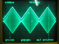
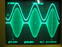
And here is the output signal, driving 500mW PEP into 50 ohms - carrier modulated 100% with a triangle wave to show off the linearity.
I will only be running my transmitter with two of the four 4CX1000A's installed, excited to the legal (Australian) limit of 400W PEP. The valves run a plate voltage of 3kV and a bias current of 250mA each, so a at only 400W PEP output, they will be really loafing along.
I will only be running my transmitter with two of the four 4CX1000A's installed, excited to the legal (Australian) limit of 400W PEP. The valves run a plate voltage of 3kV and a bias current of 250mA each, so a at only 400W PEP output, they will be really loafing along.
Attachments
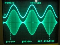
And lastly, over modulation with a sine wave. The modulator over modulates very cleanly with no funny behaviour.
All I have to do now is finish the switched crystal local oscillator board and build the microphone / audio processing board which will include signal limmiting to prevent overmodulation, brutal (8 pole) 2.5kHz low pass filtering to kill the harmonics generated by hard limiting (which works very well for AM modulation) and an audio test tone generator for tuning purposes.
A 160m crystal filter type SSB modulator is the next project in the pipeline for this transmitter.
Then all I have to figure out is how I'm going to fit a 160m dipole on my property 🙂
Attachments
Geek said:Sweet! 😀
Great linearity 🙂
Schematics?
Cheers!
Thanks!
My home computer/study is down at the moment (painting / flooring). Will post in the near future
Cheers,
Glen
Okkaayyyy....... A slight delay with getting the schematic up 🙂
Scroll down to the bottom of my page under construction here:
http://users.picknowl.com.au/~glenk/HOME.HTM
Cheers,
Glen
Scroll down to the bottom of my page under construction here:
http://users.picknowl.com.au/~glenk/HOME.HTM
Cheers,
Glen
Cheers to you Glen, that linearity is insane for not only zero-rf-detected-feedback, but low-level AM as well! 
Due to BW limitations, wouldn't vestigial sideband be more conducive to HiFi AM w/carrier though?
Cheers!
Due to BW limitations, wouldn't vestigial sideband be more conducive to HiFi AM w/carrier though?
Cheers!
- Status
- Not open for further replies.
- Home
- Member Areas
- The Lounge
- HiFi Ham band AM??