Well, if you know how to calculate and measure the ACTUAL losses you will understand...I am trying to understand your post.
Only at low frequency, given the info avalilable. I don't think you can match the Lundhals for the other things because the E+I type or conventional C core plus a conventional coil former won't give you all the advantages of the Lundhls' layout in any case...it is just simple as that.You wrote that the loss is similar to the Lundhal trafo; this is great!
Lundhal is a very good producers, if F.I.A.T. made a trafo with comparable characteristics it is a success!!
That's another statement which is quite different from saying that you match the Lundahls....The main goal was to develop a stuff with a good ratio between cost and performance.
In the link above it says this is 0.3 ohms which means 327 ohms when referred to the primary. You just need to multiply 0.3 ohms by the square turn ratio, just as you do for the primary impedance....Regarding the dc on secondary, have you measured it on this trafo?
Waltube it is sure 100% that minimum losses are ALWAYS achieved when using half space for the primaries and half for the secondaries. It is mathematical.....in practice this can vary a little bit (say 52-54% for one and 48-46% for the other, for example) and using wire of slightly different gauges in order to get the desired parameters like turn ratio, inductance etc...However if you depart a lot from that condition you will never get minimal losses. You can find the demonstration of that in any good transformer book....Regarding AC resistence, have you check it on this trafo for different frequencies?
I have only supposed you are not in an ideal condition because this is what it looks like....if you are in an more or less ideal condition the better for you but I don't believe it! It is up to you to demonstrate that....
Also, given the LIMITED high frequency response you show there are quite good amounts of stray capacitances + leakege inductance. All these things set the high frequency response.....
This is a forum Waltube and everyone is free to do what he wants if he doesn't break the rules. I make transformers for myself but don't go in the forums telling they are the best just because I made them....I don't need any approval or opinions from anyone and don't make them to sell......Normally I accept the critics about project when someone bought the parts and make it.
This means that there is a true interest to find a better solutions.
This is not your case.
How can you tell that? You don't even know me!
I have just made my point.
If you were a bit less arrogant maybe this discussion could go on in a polite way but I guess you are not here for this. You just want to SELL your OPT's.... 😱
p.s-= 45 is a number, not a name!!
That is my nick. I don't care if you don't like it....
Last edited:
how is the sound of the amp? all bartolucci transformers?
What does it have to do with this thread?
Sorry Im new i this forum.
I made Gm70, 813 triode mode 3 stage and second project 2 stage CHOKE loaded 120mH 6HV5A SYLVANIA or 6HS5 RCA RADIOTRON
Duelund cap,Russian teflon, output FIAT Transformer.
Gm70 tube biasing, 6D22 rectifier, oil cap, silver wired.
B.Regards
It might of interest to some users if you can post the schematic of your amplifier.
Base schematic driver 6HV5 tube 211, Gm70, 845, 813
Andrew polskihiend
Attachments
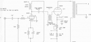
Output tubes will not last long with that anode voltage and current; for 211 it looks like 2 x maximum anode dissipation....
My new Gm70 OVERTURE work 1000V plate 125mA current with tube biasing regulated, or 1200V and 100mA.
Heater stabilized CCS with Choke 80mH and 100.000uF filtering cap AEROVOX.
Driver is driver.....actualy 6HV51000V plate.
I have made driver 6E5P in triode or pentode, 300B, 2A3
Heater stabilized CCS with Choke 80mH and 100.000uF filtering cap AEROVOX.
Driver is driver.....actualy 6HV51000V plate.
I have made driver 6E5P in triode or pentode, 300B, 2A3
My new Gm70 OVERTURE work 1000V plate 125mA current with tube biasing regulated, or 1200V and 100mA.
Heater stabilized CCS with Choke 80mH and 100.000uF filtering cap AEROVOX.
Driver is driver.....actualy 6HV5 1000V plate.
I made many driver 6E5P in triode or pentode, 300B, 2A3
polskihiend
Cathode resistor 120 OHM Cap to correct sound 0,1F, 0,15 uF, 0,47UF
Duelund Cu, VCap, russian teflon
Duelund Cu, VCap, russian teflon
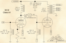
Second schematic 2 stage amplifier choke loaded.
Nice 8Hz resonator. A grid resistor at least would damp the resonance. Bad design, IMHO.
A good grid choke + a good plate choke + 2.5KV 4uF quality cap are not that cheaper than a proprer interstage.
It Is not my design.....design HIGH TENSION.
8Hz in audio its nothing for good quality speaker 20Hz to 20khz
Good choke and good cap quality only.
Im not GREEN! work 20 years with tube amplifier repair, upgrade AUDIO NOTE, CARY, AYON,LUXMAN and many many brands.
My design is commercial use..
Please give us yours project 2 stage amplifier and photo
Best Regards
Andrew from Poland
A resonance is resonance. 8Hz resonance will nicely couple with PSU resonance in the same range, especially in SE amplifiers, and also shows its effects well into the audio range, most of the bass, with a rather reactive load. A proper transformer is miles better.It Is not my design.....design HIGH TENSION.
8Hz in audio its nothing for good quality speaker 20Hz to 20khz
Good choke and good cap quality only.
And so?Im not GREEN! work 20 years with tube amplifier repair, upgrade AUDIO NOTE, CARY, AYON,LUXMAN and many many brands.
Good for you but it doesn't turn that design from poor to good. As I said you only need to remove anode and grid chokes and the coupling cap. Replace those with a good transformer. Measure it and listen to it and you'll see.
You can try with a Lundahl LL2756 or LL2762. Both are suitable for 5K source impedance. You can also optimize the air-gap for best combination of DC current and primary inductance. If the plate choke has much more DC resistance and you want the same anode voltage then you can add another RC filter before supplying the driver. It's easy. With 20 years experience you should be able to do it....
You can try with a Lundahl LL2756 or LL2762. Both are suitable for 5K source impedance. You can also optimize the air-gap for best combination of DC current and primary inductance. If the plate choke has much more DC resistance and you want the same anode voltage then you can add another RC filter before supplying the driver. It's easy. With 20 years experience you should be able to do it....
- Status
- Not open for further replies.
- Home
- Amplifiers
- Tubes / Valves
- Hi-end GM70 amplifier with only 2 stages