Geoff,
Keep making long, subjectively-based posts and you'll end up with a reputation like mine...
For those who might have missed some of my musings elsewhere, my listening experiences have closely paralleled Geoff's. I went haring off after better specs and found that I was getting further from the music--in short, I had a very expensive rig that I never listened to because it was cold and sterile. Now, whether the high/low damping factor fits into the equation or not, I don't know yet. Honestly, I'd always kinda accepted it as fact, since it's so logical, but my experience with the tube amps on the woofer panels gave me pause. It seems that others may be reconsidering the same thing. I'm looking forward to trying an Aleph on the woofers, since they tend to sound so tube-like.
Paul,
I haven't kept up with what Lynn Olsen is thinking. Got a link?
Hugh's comments on current sources/sinks (current mirrors are nothing but dual current sources) echo my own mistrust of these critters. I learned the hard way on that one. Basically, I avoid them like the plague unless they're absolutely necessary--generally when I'm using a differential as a phase splitter. The first stage in my tube amps use a 6SN7 as a (differential) phase splitter. To get good balance, you pretty much have to use a current source (sink, for the purists among you). Ah...but the driver stage is also a differential, but doesn't have to split hairs for balance. As such, I have the option of resistors or current sources. It didn't take long to make up my mind...resistor, period.
Grey
Grey
I'm not sure if your first paragraph is meant to encourage or deter me from making longer posts 🙂
Hugh
Thanks for giving me some objective reasons to account for my subjective perceptions. Unfortunately, I don't have the necessary test gear to check out these aspects and theory/simulation only go so far.
Geoff
Grey,
I haven't been able to find a link to the article(s) 'The Future of Vacuum Tubes in Audio' pts 1&2 on the web, even at his website-
http://aloha-audio.com/
They appeared in Glass Audio Vol 12 #s 3,4 2000
The first is his historical perspecitive and the second discusses his own thoughts. If you don't have ready access to these, email me with your postal address and I'll send you a copy.
Paul
From what I've read so far, Lynn Olsen knows what he is talking about and is able to link engineering and mathematics to the sonic performance of his valve amps. Worth a careful read.
Hugh
I have been browsing your website. You have been busy! Nice graphics. I notice your amp design mitigates one of the effects I mentioned earlier by using your FETs in common-source and using local feedback around them. A quick question: what is the purpose of the series base resistors of T5 and T6 and how did you choose their values?
global negative feedback
Hugh has waxed eloquent once more and has bought up an interesting subject concerning negative feedback. High damping factor is almost acheived through high open loop gain and lots of negative feeback. High feedback makes high frequency stability much harder to obtain. Designing gain stages with lower open loop gain makes for higher bandwidth. Linearity and stablity of the open loop gain of amp lessen the amount of global negative feedback needed. Many audio amps use only 6 to 20dB of negative feedback and still have have useful damping factors. I think that constant current sources have great benefits in amplifier desigh in terms PSRR and CMRR but must be designed with the same care as the gain stages. The use of cascodes, degeneration, resistive loading, and simple linear circuits make for good sounding amplifiers. Class A output stages even allow for good designs with no global feedback. It is interesting to study the history of circuit topologies and see the return to simpler and classic topologies.
H.H.
nfb and stability
Would you guys please give some more insight on nfb and good references (books) where the nfb theory is well explained especially from a more practical point of view.
As I'm among other projects working on my own amp design to get to the real insights of things. I have just reached a point where the compensation, stability etc. come to play.
I have read quite many books on the subject and also various sources on the web, but I have to admit, it's not easy to get to the real understanding of this...
I was lucky as one of my friends is a big audio enthusiast and he usually has a way to explain things from a little different angle. So he agreed to give me a little "lecture" on the subject.
Well, he explained it something like this...
***
The amplifier has many stages (usually 3-4 for bjt amp) and every stage has a pole. With each pole you'll get an additional phase shift. Usually the first pole is formed by parasitic capacitance from output of VAS to it's input. The second pole will likely be either by driver stage or output stage. So if one would like to achieve a very good stability margin, it would be desireable to drop the gain below one before the second pole frequency. This can be achieved by usual cob cap over VAS (lowering the first pole) or by other means that Hugh has also mentioned.
If one can achieve this then the amp would likely be very stabile into every load. It would be tricky though, if the second pole is not at very high frequency. Then one could use a small cap paralleled with feedback resistor to "push" the second pole up the frequency band. (I had never got the point of this cap). This will only work if the poles are exactly known and cap calculated accordingly.
Now, all previous pretty much assumes that one knows the phase behaviour (poles) of the amp. Here he suggested a method he has used. It is only applicable to amps with defined open loop gain which is not very high.
One has to cut the feedback trace as near to pickup point at amp output as possible, ground the input and then insert a sine signal into the feedback path. It would be good to use a signal source with about the same output impedance as the final stage. Now if one injects the sine wave and with an oscilloscope one signal goes from this injection point to oscilloscopes sync input and the other is used as usual, one can measure the phase at various points in the schematics while changing the frequency.
So this way it would be possible to measure and draw up the phase vs frequency characteristic for example at the output of LTP then after VAS, after driver stage and etc. If one can achieve this, it would be quite well possible to calculate quite accurately just the right values for compensation caps.
With such method it is also great that it takes into account even the feedback trace inductances and parasitic capacitances etc.
It will be hard work though as most likely the measurement have to be taken on many frequencies between say 20kHz and 2MHz and at many points in the amp. It also requires a high freq generator.
***
Do you have similar methods to achieve these results and may be even some more pointers to previous?
I will try this arrangement in near weeks and if I get results perhaps I will post them. I have one problem though, I have a generator for 0Hz-100kHz and other for 1MHz-10MHz, so I missing quite an important band : (
Ergo
Hello Ergo in Estonia.
I have a good friend from your part of the world.
Explaining how to apply NFB is a big job, too big for me in this thread. The info your friend gave you was all correct. To understand the pole-shifting capacitor thing try searching for "phase lead compensation" on the net.
Nyquist's basic theorem and most NFB theory you will read about will assume linear systems. In linear systems feedback works wonders and is your friend. In non-linear systems it becomes unpredictable and sometimes helps and sometimes hinders, depending upon the characteristics of the system. In audio amps the designer is generally trying to use NFB to correct non-linearities. Feedback is also useful for reducing the output impedance of the amp.
The three most important considerations when designing using feedback:
1) Audio amps are not linear.
2) Audio amps are not linear.
3) Audio amps are not linear.
A near-perfectly linear system will always perform better with feedback. To say an amp is so linear that it doesn't need feedback is an oxymoron.
By the way, you don't have to check stability in the frequency domain: you can inject a sharp squarewave into the feedback loop (as your friend describes how to do) and observe the output of the amp. Adjust the circuit (poles, gain) to minimize overshoot and ringing. You'll need a High-speed function-generator or you can fashion one out of TTL. Remember to check with a variety of loads.
BAM
Base Stopper Resistors
Hi Traderbam,
You write: "I have been browsing your website. You have been busy! Nice graphics. I notice your amp design mitigates one of the effects I mentioned earlier by using your FETs in common-source and using local feedback around them. A quick question: what is the purpose of the series base resistors of T5 and T6 and how did you choose their values?"
I understand your approach to be 'straight wire with gain' and math-based. This is terrific; I have no difficulty with it, except that I am not so gifted, and prefer the 'seething cauldron of empiricism', as Paul so colourfully puts it! Certainly I follow all the engineering principles, no choice there, but rather than arrive at a value with PSpice or maths I compute the limits high and low and tweak in between for best sonics.
I should mention I have tried FETs, and don't like them for anything other than Class A in SE. I have the greatest respect for the thermal robustness and resistance to reactive kickback of MOSFETs, but their self-oscillation tendency and their huge gate capacitance makes them extremely difficult to drive. In Class A this is all controllable, but in deference to tree-huggers, I prefer Class AB, and this drives me relentlessly towards bipolars. And throughout the last decade, bipolars have made huge steps forward, both in terms of beta consistency across the range and secondary breakdown characteristics. They are also cheaper than the mosfets, and their range and variety is superior.
The series base rresistors of T5 and T6 (and T7 and T8) control minority carriers in the base junctions. They thus prevent short term oscillation, particularly at turn-on and turn-off. Their inclusion in the base drive circuit also stretches the turn on and turn off events out a little (local, degenerative feedback), smoothing the transition, and giving the global negative feedback loop sufficient time to linearise the event.
In practice the inclusion of these resistors smoothes the sound. Try it; the effect is palpable. I cannot claim originality; this idea is used consistently in pro-audio, from whence much of my inspiration comes, particularly the Fender BXR300, a 350W/4R amplifier which is the stuff of legend for reliability and ruggedness.
Base stoppers have another useful function on the output devices. In the event the outputs let go, they limit driver current. In the AKSA, the drivers almost NEVER let go regardless of the mayhem to which the outputs are exposed. You might lose an output; you NEVER lose a driver.
Does this explain my position?
Cheers,
Hugh
www.printedelectronics.com
Hugh,
For some reason I had assumed you were using FETs. I think it is this site - there is a definite bias among contributors in favour of FETs here! Your circuit makes more sense to me when using bipolars. I can now understand the rave reviews I've read on your site.
Speaking of your site, which is highly informative and well-organised, just a couple of minor points: your pricing for Europe is in $US rather than Euros and your 5 design axioms are actually six.
BAM
Hi Traderbam,
Ah, thank you for your response!
Yes, not in Euros, true, but almost 90% of my product goes to North America, and I have tried to reflect the US approach in my website. Should I insert Euros as well right away?
Do you consider that with your obvious influence in these matters you might persuade more EU citizens to buy my product? (grin!)
You know, I'm an Anglo-Australian, and my Grandmother was English, but I think I've sold maybe five AKSAs into the UK!
Shame they don't seem to like Australians........!
Now Scandinavia, that's another matter. Holland, Norway and Sweden seem to buy AKSAs a lot.
Yes, six design points. I'll change that. Thank you!
BTW, what country are you in?
Cheers,
Hugh
www.printedelectronics.com
Well you know us Europeans are a proud bunch. The effort that has gone into achieving a (nearly) single currency has been huge and the transition was exceptionally smooth. Now Europe has a currency to rival the $US. It used to make sense from a manageability point of view to price in $US when there were so many different currencies but now that the Euro is available it is a bit of a slight to choose the $US as the reference currency. On this basis I would recommend you price for Europe only in Euros.
I was born in Canada but live in the UK. One day soon we'll be using the Euro too. I'll see if I can track down those 5 sales you made and find out who bought them and why - probably some Scandanavians on holiday 😛 . Having just completed an MBA I ought to be able to help you out with your European marketing campaign. Let me give this some thought. What do you do for advertising currently?
BAM
Hello Hugh, from Perth.
First to say is that I agree with your subectivist tweaking of circuit values of otherwise good engineering, in order to tune the AKSA amp module sound that I believe to be rather good, and well done. (Go Aussie !)
On your site you state that along with the kitset comes several thousand words of info regarding the module.
Is it possible to get a copy of this ?
Also, I have not seen any measured performance figures.
Of course I understand that THD etc is not the total story regarding sonics, but I am interested to know.
Also, will your modules go down to 2.6 or even 2 ohms - (With driver impedence EQ)
I'm also keen to know the overload characteristic - ie do they go nicely or softly into clip, or sound hard, or nastyish or what ?
I have reasons for asking these.
I know I am asking a biased reviewer, but that's ok. 🙂
Regards, Eric.
Hi Everyone,
Everyone is talking about the use of the bootstrap or the constant current source for quality reasons. It sounds like people are forgetting that the bootstrap allows the gate of Q5 to (possibly) go higher than the power supply. This can help achieve more symmetrical clipping and increase efficiency. But in the schematic, D1 kills this idea. Maximum positive output of the amp is +V - Vgs(Q5) which can be quite large, greatly reducing efficiency. Personally I'd remove D1 and find another way to protect the gate of Q5. Back-to-Back zeners maybe?
Doug Eleveld
deleveld said:
... It sounds like people are forgetting that the bootstrap allows the gate of Q5 to (possibly) go higher than the power supply.
I though so too. My question to Hugh and others: Would you really prefer to have a higher rail voltage for the non-output stage circuitry and NOT use the bootstrap circuitry? Or is the bootstrap circuitry serving some additional "secret" purpose?
Michael
Bootstrap with FET's
I wouldn't use a bootstrap with FET's oin the OPS. I tried it once and the amp was somewhat unstable at low and high bias currents, and it was really hard to keep the distortion low. The design I tried was almost exactly the one you posted, using an active source fixed the problem.
I wouldn't use a bootstrap with FET's oin the OPS. I tried it once and the amp was somewhat unstable at low and high bias currents, and it was really hard to keep the distortion low. The design I tried was almost exactly the one you posted, using an active source fixed the problem.
I knew I had seen the schematic of the amplifier in the first page of this thread some where before and I finally found the copies I made from an old IR application note AN-948. The design is not too bad and the info is great for some one trying to understand amplifier design.
There are o-scope pictures of the amplifier waveforms (sine and square) included in my copies at 1 KHz and 100 KHz (1 Khz and 25 KHz square wave) and all looks good. I would have like to seen pictures of the amplifier driven to maxs peak to peak though. And the reason why I am interested in this is that looking at the schematic again. The bootstrap circuit provides all the gain to the output fets. Which the positve fet recivcing most of the gain when the amplifier is driven to clipping. And so when the ampilifer is driven to maxs clipping across a load (looking at the output on an o-scope) the amplifier will clip asymmetrically (right?). Can anyone help me understand if this is correct.
Thanks.
😎
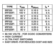
About that AN-948
I'm thinking of building that amplifier (Application Note AN-948) but I can't find irf9532 and irf532 transistors here in Greece. Can I use irf9530 and irf530 instead? Should I change some components?
I'm thinking of building that amplifier (Application Note AN-948) but I can't find irf9532 and irf532 transistors here in Greece. Can I use irf9530 and irf530 instead? Should I change some components?
Re: About that AN-948
Yes, you should be able to use IRF530 IRF9530
Difference is VERY small. Basically same transistor.
If you download the very detailed app note:
http://www.irf.com/technical-info/appnotes/an-948.pdf
you will see they even talk about 530/9530 in the text
(I think you should even be able to use IRF540/9540)
aetosa said:I'm thinking of building that amplifier (Application Note AN-948) but I can't find irf9532 and irf532 transistors here in Greece. Can I use irf9530 and irf530 instead? Should I change some components?
Yes, you should be able to use IRF530 IRF9530
Difference is VERY small. Basically same transistor.
If you download the very detailed app note:
http://www.irf.com/technical-info/appnotes/an-948.pdf
you will see they even talk about 530/9530 in the text
(I think you should even be able to use IRF540/9540)
Attachments
Done
OK my friend. I will try it and will let you know how it works (if it works because I have a bad history with mosfet amplifiers. I tried to make the one found in http://www.redcircuits.com/Page2.htm
but it was a total failure. Something in the PCB, wich I designed, was wrong, I didn't make to find out what, and abbadoned.) . Thank you for your interest.
Something more!!
I see you have built the amplifier foun onthe site I mentioned (http://www.redcircuits.com/Page2.htm). Does it work?Do you have a PCB layout? Which one of the two amplifiers would you suggest?
I see you have built the amplifier foun onthe site I mentioned (http://www.redcircuits.com/Page2.htm). Does it work?Do you have a PCB layout? Which one of the two amplifiers would you suggest?
- Status
- Not open for further replies.
- Home
- Amplifiers
- Solid State
- HEX-FET 60W/4ohm Amplifier