Hello
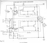
Here's a 20 watt amp, very simple but sound good, for those who want a small power amp, it's from Fairchild Semiconductor, 1974
Here's the shematic;
For the output darlington transistor you can use 2N6388 and 2N6668 , made by On Semiconductor, cost arround $1. at Mouser.com
I did made one for a friend, few years ago, it was sound very good.
Here's what I did get on my HP333 distortion analyser.
Distortion vs frequency
1khz .07 %
10khz .08 %
20khz .1 %
30khz .12 %
Distortion vs power output at 1 khz
.5 watt .17 %
1.5 watt .12 %
4 watt .05 %
12 watt .16 %
17 watt .5 %
20 watt 4 %
Try it and say your listening impressions.
Gaetan
Here's a 20 watt amp, very simple but sound good, for those who want a small power amp, it's from Fairchild Semiconductor, 1974
Here's the shematic;
An externally hosted image should be here but it was not working when we last tested it.
For the output darlington transistor you can use 2N6388 and 2N6668 , made by On Semiconductor, cost arround $1. at Mouser.com
I did made one for a friend, few years ago, it was sound very good.
Here's what I did get on my HP333 distortion analyser.
Distortion vs frequency
1khz .07 %
10khz .08 %
20khz .1 %
30khz .12 %
Distortion vs power output at 1 khz
.5 watt .17 %
1.5 watt .12 %
4 watt .05 %
12 watt .16 %
17 watt .5 %
20 watt 4 %
Try it and say your listening impressions.
Gaetan
The SAP devices by Sanken would work well here too.
Datasheet:
http://www.farnell.com/datasheets/82862.pdf
Cheers,
Glen
Datasheet:
http://www.farnell.com/datasheets/82862.pdf
Cheers,
Glen
Hi
Without emitter resistors in the darlingtons , I'm afraid the quiescent current is not stable , and thermal runway can occur ...
Jorge
Without emitter resistors in the darlingtons , I'm afraid the quiescent current is not stable , and thermal runway can occur ...
Jorge
Tube_Dude said:Hi
Without emitter resistors in the darlingtons , I'm afraid the quiescent current is not stable , and thermal runway can occur ...
Jorge
No. In that design the darlingtions are biased cut-off (ie < ClassB), so emitter resistors are not required, as there is no quiescent current.
It would generate heaps of crossover distortion.
That's why I mentioned the Sanken parts..........
Cheers,
Glen
Probably worth increasing the bootstrap cap to 100-220 uF, 50v - should improve the bass response below 30 Hz. Also a small bypass cap - say 1-22 uF, around the diode/resistor Vbe bias chain should improve the highs.
A small miller capacitance of around 33-100pF between the base and collector of Q1 should help suppress AC instability.
I've built something similar to this, but with a Vbe multiplier for crossover biasing, bias stabilization resistors of 0.2R in the emitters of Q2 & Q3, and 2N6054/59 TO-3 output darlingtons.
AHhhhhh!Output coupling cap!
AH, a modern design... 🙂
was popular almost 40 years ago.
Kapibara said:This amplifier is class B or class AB ?
It's only a bad joke now in 2007...
Class AB.
40 years ago ? I'm not 40 years old (27!) but I DO know that they didn't have PNP power transistors worth a damn, let alone compound darlingtons with built in flywheel diodes!
I'd say early 80's DIY design, borrowing from the geranium amps of the 70's.
40 years ago ? I'm not 40 years old (27!) but I DO know that they didn't have PNP power transistors worth a damn, let alone compound darlingtons with built in flywheel diodes!
I'd say early 80's DIY design, borrowing from the geranium amps of the 70's.

Attachments

That certainly does look like a 70's app. note. It's class C, almost to class B. A little more bias so the junctions are really almost on might help it out a lot. Even 1 mA of current would really help. It is not in any danger of going into thermal runaway as long as the bias components are on the heat sink or transistor cases.
-Chris
Fer sure!Never liked them....... colored sound
-Chris
Hello
Hey guy's I know it's a 30 years old circuit, but it's so simple and it's working since I've built one 8 years ago, it was good as a so simple circuit can be and I heard much worse amp with 5 time more transistors, he he he, but it's an easy amp for the beginer.
Linuxguru suggest those mods;
-------
Probably worth increasing the bootstrap cap to 100-220 uF, 50v - should improve the bass response below 30 Hz. Also a small bypass cap - say 1-22 uF, around the diode/resistor Vbe bias chain should improve the highs.
A small miller capacitance of around 33-100pF between the base and collector of Q1 should help suppress AC instability.
-------
Gaetan
Another basic improvement to look at here is an active Vbe multiplier. 50-100mA Iq would probably do wonders for the sound and the HF distortion.
I really like the simplicity of this design - great little starter amp.
I really like the simplicity of this design - great little starter amp.
Hello
I did a schematic with the Linuxguru suggested mods, and I added a 500 ohm bias trim pot and a 15 pf bypass cap on the nfb resistors, but no active Vbe multiplier, better to keep the amp simple. All mods have a * near them. And if I've done error in the schematic mods, no problemo just tell me.
Bye
Gaetan
Attachments
Also worth considering is a small-signal darlington for Q1 (or an emitter-follower driving the base of Q1), with the appropriate changes for DC biasing.
The proof of the pudding is in the eating thereof. Let us know how it sounds after the mods - better or worse?
The proof of the pudding is in the eating thereof. Let us know how it sounds after the mods - better or worse?
You should reconsider. A small signal transistor, 2 fixed resistors and a pot will be a lot cleaner and perform better than the diode/pot string currently in the circuit.
- Status
- Not open for further replies.
- Home
- Amplifiers
- Solid State
- Here's a 20 watt amp, very simple but sound good