That link shows the 6BE6 as a mixer. The gains for the two inputs are about 3:1. Making it into a Concertina phase splitter in addition to being a mixer would limit its performance. You might get a gain of about 1 on one grid and about 1/3 on the other grid.
Instead, just use a dual triode. You could build a cathode coupled phase splitter with a current source in the cathodes. Then you apply one signal to one grid, and the other signal to the other grid. They will mix that way. They will be equal gain. You will get combined (mixed signals) with 2 different phases out. But the Relative phases of the original signals will have been switched. This might be a little hard to follow, but will work.
What is the rest of the application you are doing?
The Heptode was used in the older TV sound stages to demodulate FM sound.
Take a look here; EH90 as fm demodulator - UK Vintage Radio Repair and Restoration Discussion Forum
Take a look here; EH90 as fm demodulator - UK Vintage Radio Repair and Restoration Discussion Forum
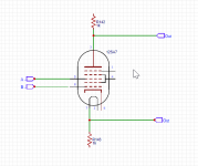
Mixer tubes, like the 6BE6, are designed so that the 2nd signal grid operates after a virtual cathode again, due to the positive shielding grids around it that absorb grid "reflected" electrons and prevent the 2nd signal grid's field effects reaching the cathode. Giving a product result. What is needed for an audio "mixer" is a sum result.
Fortunately, just such a tube exists. The sheet beam deflector.
http://tubedata.milbert.com/sheets/093/6/6JH8.pdf
It can do sums, and products (with grid 1). An analog computing element all in one tube. And very accurate. (low distortion)
Put signal 1 on one deflector, and signal 2 on the other deflector. Outputs of (S1 - S2) and (S2 - S1) then appear on the dual plate outputs. Note: One audio signal is sign flipped, just like with the dual triode scheme. Could invert that signal before using it. But then you are back to two tubes, and no chassis hole savings. ( the tube is effectively a differential stage above an internal CCS tail, tail current controlled by grid 1 )
Last edited:
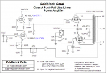
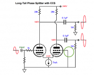
The plan is to build a small 25W practice bass amp with two inputs (One for a USB to play tunes to) so I would replace the 12SL7 shown in the KT88 with the Long Tail splitter and the second input would go where the green circle is. I realize this will require some modification, any advise would be appreciated I have a 12AX7 would that work well? I am also not sure what the CCS is doing for the circuit here.
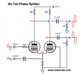
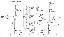
There is also a no tail splitter, it says "We could replace the constant-current source with a common cathode resistor and use a coupling capacitor to attach to another input signal, with the same phase, but half the amplitude." Which may actually be good because I expect the USB output circuit board (The unit I have comes with built in preamp) to be much stronger than the bass guitar input. In any case I will have to build a preamp at some point. Was looking at the Ambelic F-2B.
There is also a no tail splitter, it says "We could replace the constant-current source with a common cathode resistor and use a coupling capacitor to attach to another input signal, with the same phase, but half the amplitude." Which may actually be good because I expect the USB output circuit board (The unit I have comes with built in preamp) to be much stronger than the bass guitar input. In any case I will have to build a preamp at some point. Was looking at the Ambelic F-2B.
Attachments
The plan is ... two inputs...
Then use two resistors, like 99.99% of audio mixers do.
Yes, that app-note does show an audio mixer. The boys in the lab must have been out of good ideas that day.
Yes, there's a whole field of Analog Computing to plagiarize from. But to get a "Sum" (what we call mix) they use two resistors. They may add an op-amp to reduce interactions and preserve precision gain; that's moot for two user-controlled inputs (diddle knobs until happy).
The Cathodyne depends on NO current escaping the Plate-Cathode path. The Hexode has very significant current in G2 G4.
The Cathodyne's heart is a Cathode Follower. The cathode follows the input. Now apply two inputs. This becomes like a worker with two bosses. Who to obey?? (I am working a crew on my house, and must keep my mouth shut, remember that the Boss who I hired has to give all the orders or the workers get conflicted.)
Design your amp around readily-available tubes. Not tubes you "have". Many lucky-dip tubes turn out to be bad. If good today, what when it finally fails? (True, the 6BE6 will probably be available for your lifetime.)
Last edited:
If you want to use the Oddblock amp, do not try modify it by taking out the 12SL7. The negative feedback goes to that tube. Now you have to refigure all that. Unless . . .
If you use a long tailed splitter, the point of a current source is that the 2 phases will have the same amplitude as long as the plate resistors are matched. Using a resistor in the cathodes requires you to use un-balanced plate load resistors, and you should tweek that for every tube you put in there, even if they are the same type.
The Oddblock has a current source in the output tubes. If you use a long tailed splitter to drive the output tubes, then you ought to use individual self bias resistors and individual bypass caps on the output tubes cathodes (eliminate that current source). Then the negative feedback should go to the grid of the right hand splitter tube, and the signal input to grid of the left hand splitter tube.
As stated earlier, you can build a mixer using resistors.
I saw this posted in a forum, is this a good general rule? I know you have to verify that the current is as close to the recommended standard operating perimeters in the data sheet as well. This is a general RFC as I am looking at what you all do when dropping a preamp tube such as the 12ax7 into a circuit you are designing.
Quote:
"As for circuit mods for 12AX7, it depends on the topology. If a straight voltage amp, have an anode load resistor typically 100K and choose a cathode resistor for B+/2 (usually 820R for a healthy tube)."
Quote:
"As for circuit mods for 12AX7, it depends on the topology. If a straight voltage amp, have an anode load resistor typically 100K and choose a cathode resistor for B+/2 (usually 820R for a healthy tube)."
I saw this posted in a forum, is this a good general rule? I know you have to verify that the current is as close to the recommended standard operating perimeters in the data sheet as well. ....
"...for 12AX7, ...straight voltage amp, have an anode load resistor typically 100K and choose a cathode resistor for B+/2 (usually 820R for a healthy tube)."
That "general rule" does work.
"B+/2" is not a stand-alone rule.
Never design for an "unhealthy" tube.
You sure do not have to get close to "recommended standard operating perimeters"... those are usually Test Specs, NOT best operating points. You can go very far away. Usually not much "up", because the test-specs are also "show-off" specs that work the tube near max current to get impressive Gm Rp numbers. You can go much lower current but you lose gain-bandwidth product.
And for a contrary point of view: Leo Fender got rich with plate at 70% of B+ and Rk of 1.5K. (Rich when he sold-out the company.)
You should also read Radiotron volt-amp design notes.
It is sounding like the design process is not a static process, where you just calculate all the values based on datasheets and documented design knowledge. This is just a good starting point. The process is also a "live" observational process as well. So would it be part of the process to use, say a 2K pot, on the cathode and then adjust the value while observing the results on the oscilloscope. When the optimum result is found you can measure the pot resistance and then use the closest standard resistor value. That also tubes vary from tube to tube (Especially in used tubes) so an individually optimized amp would be superior to one just built off a standard design. What about using a trim pot so that over time the value could be adjusted as the tube ages?
It is sounding like the design process is not a static process, where you just calculate all the values based on datasheets and documented design knowledge.
Design is never static, except in introductory textbooks which assign one detail of a complete problem.
...use, say a 2K pot, on the cathode and then adjust the value while observing the results on the oscilloscope.
One aspect of engineering design is to know your materials and how much they vary. You can now (since 1920s) buy steel of known strength. While wood grading has gotten better than raw-cut logs, a wood designer has to allow for any individual stick being much weaker than average. The wood-guy over-builds. With tubes of uncertain gain, the same thought leads to higher B+ and Ik, not individual diddling. Of course in DIY, diddling may be considered Entertainment, not Expense.
...an individually optimized amp would be superior to one just built off a standard design. What about using a trim pot so that over time the value could be adjusted as the tube ages?
Again: rational design suggests over-building so that "any" stick, beam, or tube will perform amply well. I have had an old saggy kitchen floor where every couple years I had to go under and re-shim the boulders under the log-beams. That gets to be a drag.
B+/2 makes sense for a transistor, which has a very small collector-emitter (or source-drain) saturation voltage compared to B+."B+/2" is not a stand-alone rule.
B+/2 makes very little sense for a 12AX7, which may refuse to saturate below 100 volts when fed from a 300 volt B+. Since the anode can swing from 100 V to 300V, the midpoint (of anode swing) is now 200 volts, not 150 volts.
Not coincidentally, 200 volts happens to be 2/3 B+. More on that in a moment.
Leonidas was almost certainly copying from the back of a valve data book, and the circuit he copied used triode "Golden Ratio" biasing. The recipe is to use an anode resistor that equals twice the internal anode resistance (plate resistance in American), and then choose the cathode resistor to set the anode to 2/3 B+.Leo Fender got rich with plate at 70% of B+ and Rk of 1.5K.
This results in maximum output headroom, and probably more importantly, a circuit that will work well in spite of all manner of tolerance variations in resistors and triode parameters. Voltage gain becomes 2/3 mu, another simple and useful result.
There is an elegant description of Golden Ratio biasing on page 22 of Merlin Blencowe's chapter on "The fundamentals of amplification". He has kindly made this particular chapter downloadable, free, from his website, so download, flip (virtually) to page 22, and have a look: http://www.valvewizard.co.uk/Common_Gain_Stage.pdf
-Gnobuddy
...almost certainly copying from the back of a valve data book
Well, let's look in the back of the book, as I agree Leo probably did. (See Attached.) His plan does not match the suggestions. Mis-copy? Cut-and-try? We will never know.
But these suggestions are NOT any *specific ratio*. They cover a 10:1 range of resistances.
...and the circuit he copied used triode "Golden Ratio" biasing.
I hate to disagree with Merlin, but classically "Golden Ratio" is 1.618, not 2/3 or 1.5. But maybe the World Bank has changed the value of "golden".
use an anode resistor that equals twice the internal anode resistance.., and then choose the cathode resistor to set the anode to 2/3 B+....
This is a curve-ball. As you increase plate resistor, plate current falls, plate resistance rises. Can you actually find "twice anode impedance"?? Do you need to?
The gain would then be 2/3rd Mu.... UN-loaded. What is the point of an unloaded tube? Even if we have huge resistances, capacitance always sucks, and tends to be a few hundred K at the top of the audio band. (Which is WHY we use the tubes and resistors we do.)
I'm also displeased at the assertion "...it so happens that this is also the condition that results in maximum power being delivered to the load!", since there is no load, and for some load conditions 2*rp is not a good fit. (This optimization is given in the MIT Radar book.)
Attachments
- Status
- This old topic is closed. If you want to reopen this topic, contact a moderator using the "Report Post" button.
- Home
- Live Sound
- Instruments and Amps
- Heptode mixer inverter