Excellent response thanks. The original now scratchy pots supplied by Ron Welbourne were 100R 5W according to the parts list. This seems massively overrated as most pots I have been looking at are 2W at best.
Whats you opinion on this?
Whats you opinion on this?
And hopefully one last question.
I have calculated that the resistance of each leg goes from 50R to 8R when a 10 ohm resistor is placed in parallel. Can I assume this will not have an effect on the way this little circuit performs?
You can work out I am not skilled at this and want to avoid an electrical disaster 🙂
I have calculated that the resistance of each leg goes from 50R to 8R when a 10 ohm resistor is placed in parallel. Can I assume this will not have an effect on the way this little circuit performs?
You can work out I am not skilled at this and want to avoid an electrical disaster 🙂
Can I assume this will not have an effect on the way this little circuit performs?
It will have a huge affect: the resistors will carry the plate current so that the wiper of the pot no longer does. That will reduce hum when the pot is correctly adjusted and decrease distortion and noise that result from all the current going through the wiper.
The filament only has 2.5 volts across it for the 45... I would be happy with a 2W pot no problem.
As to the parallel resistor, I can't really say... I would be inclined to use the two 10R resisters in series, ground the junction where the two meet, and leave out the pot and see how it does. It's been years since I messed around with the 45 (and direct heated types in general) but with such a configuration I never needed hum-dinger pots and anything fancy, two resistors worked fine for me, but I also tightly twisted my filament wires by clamping one end of a pair of wires in a vice, and clamping the other end of the pair into the chuck of a drill. Spin them up until it's super-duper tightly twisted, and route them correctly, and they are (usually) dead silent.
As to the parallel resistor, I can't really say... I would be inclined to use the two 10R resisters in series, ground the junction where the two meet, and leave out the pot and see how it does. It's been years since I messed around with the 45 (and direct heated types in general) but with such a configuration I never needed hum-dinger pots and anything fancy, two resistors worked fine for me, but I also tightly twisted my filament wires by clamping one end of a pair of wires in a vice, and clamping the other end of the pair into the chuck of a drill. Spin them up until it's super-duper tightly twisted, and route them correctly, and they are (usually) dead silent.
Winnie - Can you post some well-lit, in-focus photos of your amps? Also, is there any initials and date written on the PCB? A friend of mine and I used to build the factory-wired amps for Ron many years ago.
OK great, but my naive question was more about the fact I will be changing the overall resistance of a part of a circuit and will it make it so that another component may overheat or fail early - just being safe 🙂It will have a huge affect: the resistors will carry the plate current so that the wiper of the pot no longer does. That will reduce hum when the pot is correctly adjusted and decrease distortion and noise that result from all the current going through the wiper.
Last edited:
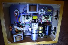
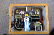
OK, here are the pictures of my amp as received and after Slawa of SW1X had worked on it.
When I got it, the solid state rectifier was in operation and it sounded mediocre at best. Slawa reinstated the valve rectification and added some other bits (capacitors?). He was pretty damming of the quality of many components particularly the bits in the SS rectifier.
Anyway now it sounds brilliant, aside from the scratchy hum pots.
Last edited:
Winnie - Can you post some well-lit, in-focus photos of your amps? Also, is there any initials and date written on the PCB? A friend of mine and I used to build the factory-wired amps for Ron many years ago.
Did you have a chance to look at the pictures?
That was a kit.
I'd genuinely like to see a schematic of the mods, it looks quite interesting! The DRD was always a funky design, not in the overall idea, but in the way it was implemented by Ron.
I'd genuinely like to see a schematic of the mods, it looks quite interesting! The DRD was always a funky design, not in the overall idea, but in the way it was implemented by Ron.
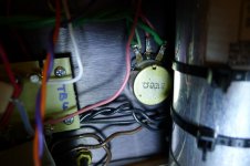
I would recommend running ground wires from those pieces of iron mounted to the wood base to wherever the safety ground connects to the chassis.
It wouldn't be a terrible idea to do this to the cap either.
It wouldn't be a terrible idea to do this to the cap either.
That was a kit.
I'd genuinely like to see a schematic of the mods, it looks quite interesting! The DRD was always a funky design, not in the overall idea, but in the way it was implemented by Ron.
Hi
The mods were carried out by Slawa at SW1X.
SW1X Audio Design Technology | SW1X Audio Design
Slawa's main problem was the use of an SS rectifier. All the parts for reinstating the valve rectification were present so he got it working with a "better" valve, a vintage 5U3C. He couldn't believe the cheap rubbish components in the SS rectifier and described it like having wings but staying on the ground. He also played with capacitors. Sorry, I don't understand much more than that.
Initially the amps hummed to the point of (my) distraction through the speakers. That is all but gone now after the mods, and its sounds absolutely magic with vintage 45 RCA valves through my open baffle speakers.
I was looking at the circuit diagram for the star chief and wondered which components in mine would be worth upgrading for better SQ
I have the circuit diags (like a foreign language to me) and could attach them if it helps.
OK, have bought a pair of Alan Bradley 100 ohm pots (2.25W) to replace the scratchy ones in my amps. All good so far, but I would like to also do the mod by installing Alan Bradley 10 ohm resistors in parallel to the potentiometer tracks. Here is where my limited knowledge of electronics rapidly runs out.
The 10 ohm resistors installed in parallel will take the overall resistance of each side from 50 ohms to about 8 ohms. 1/R =1/R1 +1/R2
Now the heater circuits are about 2.5 volts, so using I = V/R, going from 50 ohms to 8 ohms will mean current going from 0.05 amps to 0.3amps
Equally using Watts = IxV, the wattage moves from 0.125W to 0.75W - surely this means things will get hotter.
Please can someone put me out of my misery and explain this to me.
Last edited:
When you calculate dissipation, you're calculating the total dissipation between a resistor and half the track of a pot.
For sizing the resistor, you have 20 Ohms across 2.5V, which is about 1/3 of a watt dissipated across the whole 20 Ohms. Based on this, I'd use 1/2W parts.
On the other hand, if you turn the control fully one way, you'll have all 2.5V across 10 Ohms, which would suggest more like a 2W part is appropriate.
Or you could just put the 100 Ohm pot in there without any resistors.
Exactly right. 🙂
Or you could just put the 100 Ohm pot in there without any resistors.
I was taken by this comment earlier in the thread regarding the additional resistors
"It will have a huge affect: the resistors will carry the plate current so that the wiper of the pot no longer does. That will reduce hum when the pot is correctly adjusted and decrease distortion and noise that result from all the current going through the wiper."
I am guessing that having bought quality, military grade potentiometers this will probably not be so important to do.
I would recommend running ground wires from those pieces of iron mounted to the wood base to wherever the safety ground connects to the chassis.
It wouldn't be a terrible idea to do this to the cap either.
Is this for SQ or merely for safety. If I plan it, I can do star earthing 🙂
- Home
- Amplifiers
- Tubes / Valves
- Help with Welborne DRD 45 amp