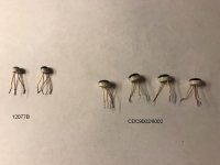
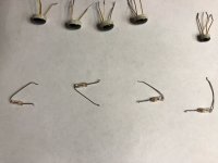
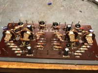
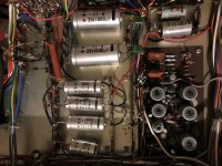
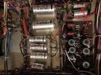
A coworker's father purchased this back in the 60's or early 70's I guess. He asked If I could look at it as it keeps blowing the fuse. What I found was a paper clip inside the unit. I first checked the final transistors and One was dead short and the two 0.5 ohm suzuki wire wound's where burnt on that channel.
I found replacements (NOS) NEC 2SD154 Transistors and replaced them with the resistors. Nothing else seemed shorted with a quick check around the driver board.
Turned unit on and no smoke! but 24 volt on the speaker outputs...Both channels!
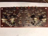
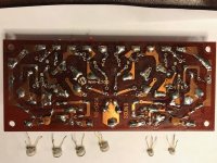
Digging further, found one of the diodes leaking. I pulled the bias and driver transistors and did the normal ohm check.
Here is the question???
I get meg ohm readings from base to collector and base to emitter but no readings from collector to emitter. Almost like it's open. Is this normal for these very old transistors?
I also found one open capacitor. Fun Fun...
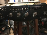
It's similar to a Sansui AU 555A stereo.
I found replacements (NOS) NEC 2SD154 Transistors and replaced them with the resistors. Nothing else seemed shorted with a quick check around the driver board.
Turned unit on and no smoke! but 24 volt on the speaker outputs...Both channels!
Digging further, found one of the diodes leaking. I pulled the bias and driver transistors and did the normal ohm check.
Here is the question???
I get meg ohm readings from base to collector and base to emitter but no readings from collector to emitter. Almost like it's open. Is this normal for these very old transistors?
I also found one open capacitor. Fun Fun...
It's similar to a Sansui AU 555A stereo.
Attachments
24 volts on the speaker outputs... that might be normal if they are capacitor coupled and with no bleed resistor.
Voltage boost from the speaker through a resistor?
No - if it's a single supply amplifier, the output will normally be biased at half the supply voltage. This DC offset is then removed by the output capacitor. However that capacitor has to charge on power up - and often it does this through the speaker.
If you have no speaker connected to the amplifiers output, the capacitor doesnt charge and when you measure with a high-impedance multimeter, you see the DC offset.
Voltage boost from the speaker through a resistor?
No - if it's a single supply amplifier, the output will normally be biased at half the supply voltage. This DC offset is then removed by the output capacitor. ................
Some designs do actually have the bootstrap connection made via the output coupling cap. It saves using another cap for that function.
Its a bit of a stretch though to imagine a design that would give such a high voltage at the output.
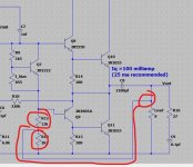
This is one design I actually built many years ago. Now if the two resistors circled were swapped around you would get a high DC voltage at the output when no load was attached.
Attachments
Wow thanks... I am in the middle of drawing a schematic for the driver board. I found some open caps and one leaking diode. I was reading and people use 4148 diodes to replace these old one. I checked and could not find any small bad transistors. Thank goodness!
Scott
Scott
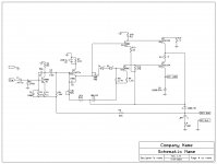
Driver board Schem
There is one more board connected to this but I did not draw it.
So is this a Capacitor coupled output?
Also Any harm using 1n4148 diodes or would the bias have to be adjusted?
Thanks all... I would have never known what was wrong... Guess just the one 2sd154 and the .5 resistors that burned.
BTW... Most of the caps 99% are good, most are Elna.
Attachments
1n4148 are generic and appear to be big enough for this circuit.
Pots can lose contact over the years due to oxidation. I'd clamp VR2 with another 1n4148 to make sure output transistor idle current doesn't take off in that case.
Something this old, make sure any mica washers under the output transistors are replaced. They are reliable for about 40 years. Use heat sink compound. Or use silicon rubber heat sink washers if you can get some. those need no heat sink compound.
The volts on the output cap are because of the bias resistor R2. Just as Mooly predicted.
Vcc is not listed, 70 v maybe? Early amps used a lot of rail voltage because early power transistors had bad gain. 5 maybe? If it is a 50 w/ch amp, you can check output voltage on speaker or 8 ohm resistor to check how good the caps really are. Most new repair amateurs think capacitance is the measurement of a 40 year old cap, when in fact the bad ones increase in capacitance a little. If the amp can put out 20 vac on a 8 ohm resistor, the rail caps have adequately low ESR. V=sqrt(Z*P) for power rating & speaker impedance of that rating. You can buy a $120 ESR meter but I found it to be a waste of money. Lot of "excessive leakage" readings for caps in parallel somehow. I've found $40 DVM produce random numbers on music on AC scale, use a $25 analog vom with 20 or 50 vac scale. In tractor dept of a farm supply or sometimes at discount stores. I excite the amp for these tests with a pocket radio. Cheaper than a signal generator, usually $3 at a charity resale shop.
Last edited:
The schema contains errors. R9 and collector Q3 goes to +Vcc. Incorrectly connected and polarized Q1.
D1,2 can be installed 4148 and others. You can take TO-126 in diode connection and install it on the radiator of the output transistors.
Pot VR2 (500)- bias .
Pot VR1 - setting 1/2Vcc in output .
D1,2 can be installed 4148 and others. You can take TO-126 in diode connection and install it on the radiator of the output transistors.
Pot VR2 (500)- bias .
Pot VR1 - setting 1/2Vcc in output .
Last edited:
I was carful when drawing this but... I Will double check again though...😱
Dang, And I just put it back together...🙁
Thanks for the knowledgeable input.
Dang, And I just put it back together...🙁
Thanks for the knowledgeable input.
Attachments
Last edited:
Attention! Transistors are easily damaged when soldered. There is a break in the conductors inside. Hence the megohm. You will not find such transistors anymore. Choose modern counterparts from those available to you ТО-92 (W), TO126.
TO-126 is BCE pattern. These old parts are EBC. You have to twist the leads around, which damaged the pcb one time I tried it.You will not find such transistors anymore. Choose modern counterparts from those available to you ТО-92 (W), TO126.
You can usually buy one kind of EBC transistor in TO18 at newark.com TO18 is metal, so with a big enough heat sink you can use them up to 10 watts. I bought 2n5682 npn two years ago.
Surplussales of Nebraska has TO5 EBC transistors from surplus auctions he attends, but I was unable to find any over 60 v Vceo this year. Appeared genuine; tiny fab houses that wouldn't likely be counterfeited.
For lower wattage input transistor TO92 comes in EBC and also BCE. for EBC try MPSA06/56.
It's A SYMPHONIC MODEL 5204WA with a Garrard model 2025TC turntable. Don't know the year and no info on it that I could find except on this forum with some of you very knowledgeable technician's.
Really appreciate the help...
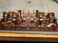
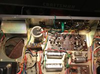
It's all back together. I replaced the final transistors 4ea (2SD154). Two of the .5 ohm wire-wound resistors. All the electrolytic's on the driver board and a 270 ohm carbon resistor.
Unit turns on with no smoke!😀 After about 3 or 4 seconds, the sound comes through the speakers. I measured the dc offset with no music playing and the speakers hooked up and it shows 0.00 vdc on both channels. with the speakers unhooked it shows about 15 vdc. The power supply has 50 vdc and about 3mv of ripple.
It sounds very good, almost tube sound.
Still curious if I should replace them 1000uf/35v caps for the speaker outputs?
I works and get's plenty loud and very clean sounding so I most likely won't.
Thanks All for the help as I continue to learn, seem's it never stops
Really appreciate the help...
It's all back together. I replaced the final transistors 4ea (2SD154). Two of the .5 ohm wire-wound resistors. All the electrolytic's on the driver board and a 270 ohm carbon resistor.
Unit turns on with no smoke!😀 After about 3 or 4 seconds, the sound comes through the speakers. I measured the dc offset with no music playing and the speakers hooked up and it shows 0.00 vdc on both channels. with the speakers unhooked it shows about 15 vdc. The power supply has 50 vdc and about 3mv of ripple.
It sounds very good, almost tube sound.
Still curious if I should replace them 1000uf/35v caps for the speaker outputs?
I works and get's plenty loud and very clean sounding so I most likely won't.
Thanks All for the help as I continue to learn, seem's it never stops
Attachments
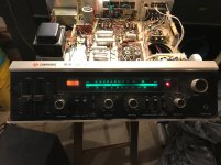
How old is that unit, 1977??
My guess:
Attachments
Wow thanks... I am in the middle of drawing a schematic for the driver board.
I'm curious what you use to draw schematics, I need to find something simple, thx.
Ross
- Home
- Amplifiers
- Solid State
- Help with very old Transistors