GM,
That's fair enough, and my goal is eventually to learn/understand more of the physics, although I'm definitely still at the "doodling with design programs till you get what seems suits" stage of the process!
I think I already understand the significance of most of the T/S parameters (although practically implementing that knowledge is something else) but interesting to hear that free calculators often fall apart outside of a narrow range and just flatline things. I'll take a look at those links, in any case.
Re: software, I've heard the same about Akabak. I know WinISD used to be a popular beginner-friendly option, but I have no idea if it is still a good choice these days. I've also seen suggestions for VituixCAD but I don't know if it is another one that can do a lot but is excessively complex for beginners. Re: what you use, isn't Hornresp just for horns, as the name suggests? (I think those are a few steps further down this path than figuring out bass reflex enclosures!)
This might help. https://p10hifi.net/FAL/downloads/Changing-Port-Size.pdf
Basically: Pick driver. Sim box. Convert vent given to slots using he above,
dave
Basically: Pick driver. Sim box. Convert vent given to slots using he above,
dave
Last edited:

That does indeed help, thanks. I think when I was fiddling around with the numbers previously I was keeping radius/diameter in proportion to length, rather than area. Going by the equations in that document, the numbers I'm getting for standard round port + vs. those in existing Planet10 plans for the same driver and enclosure volume are now much closer than what I was getting before.
And I've just realised my assumption re: Hornresp only doing horns was incorrect. Have just installed it to see what it does, and realised the wizard includes pretty much everything else, too. Silly me for taking the name at face value!
If you need software that is easy to start with, WinISD is good to learn the basics, Virtuixcad is the most preferred program for ported cabinets, also because it's a total package (also usefull to make crossovers and simulate from measurements. Hornrsp is quiet difficult to learn, but very powerfull if you understand the program. But knowing the math behind it is the best (see GM his comment).
Back again! Have had a play around in WinISD and am now comfortable with 'the basics' there and will likely get into some of the other software down the track. This has led to some questions about specific effects of varying port parameters (for a fixed tuning frequency) in Dave's xOnken styles. Thus, I'm guessing Dave might be best placed to answer this stuff, although if anyone else can chip in that works too.
Essentially, I've figured out that for the driver I'll be using (going by manufacturer specs, which I know may be a bit off) I'll get a fairly flat frequency response with about a 17L internal volume with a port tuned to about 54Hz (Fs of my driver is 60Hz), which comes to about a 5cm diameter, 8.8cm long tube, or equivalent. Using Dave's previous PDF for converting port lengths and then changing the area into multiple rectangles, if I go with the vents in the plan for this driver I'd seen in an old thread, (which had 6 ports of 1.2x7.5cm dimensions), I get a length of about 24cm for the same tuning frequency, which would fit within about a 30cm deep box including loss of length at the front with the 45-degree cut, and with enough clearance to the back wall, which is a box depth that I can in turn use to get to my target volume in one of the typical acoustic ratios to minimise standing waves.
However, it would be possible to get the same tuning frequency with the exact same port area but with different aspect ratios (e.g. go to 1x9cm, or 1.5x6cm, and so on) and the same port length, or for that matter a larger or smaller area with a different length. Without either learning how to do a lot more complex simulation than I'm currently capable of (and I think Dave mentioned his quasi-aperiodic MiniOnken stuff can't really be simulated regardless), or building a bunch of different enclosures and measuring their outputs, I don't think I'd have any way of figuring out what these changes would achieve (or for that matter, which is the most optimal one for my purposes). So I thought I'd ask if someone who's made a bunch of these and/or who has a lot better understanding of the theory can comment on what happens when these things are changed.
Basically, the two parameters I'm wondering about changing are the width of the ports (without changing their total area, so the tuning frequency isn't impacted); and the overall area of the ports (again for a fixed tuning frequency, by changing length to keep this the same). The obvious things I can think of here are that there are physical space limits within the enclosure, that if the port gets too large in diameter port resonances may reach frequencies where they will cause trouble (which I believe was mentioned as a concern more for traditional Onkens than Dave's designs), if the port is too small it may generate port noise, and that if the ports are too short the double-wall structure will end up less rigid because only a short part is actually doubled and the rest of the length is just a single bit of wood. I'm not sure if these are as big a problem with a bunch of rectangular slots as they would be with one big round port, or if the double-wall strength thing is particularly significant or not. And then regarding port width, I'm guessing that narrower means more resistance and thus a greater aperiodic effect, which has fairly well-documented impacts on frequency response that I can look up - from memory, basically pushing things closer to a sealed enclosure's response. But I would not be surprised if there are also other impacts on the sound of each of these if pushed to extremes.
Moving on from that, I'd presume that if trying to maximise the aperiodic MiniOnken thing, the approach after simulating box volume would thus be to change the port area/diameter to get the longest ports that can fit within the overall enclosure without getting closer than say 3-4cm from the back wall in the sort of enclosure size I'm dealing with (this dimension is a vague guess from earlier comments and looking at some of the Planet10 plans). But again, I don't know what different shape ports for the same overall area would do so it has hard to decide how to lay them out.
Can anyone enlighten me if my conjecture here is right, or if there are other impacts I've not considered?
Oh, and one more thing I forgot to ask in that last wall of text - is there any sort of rule of thumb relating port area to the driver's cone area, either generally for bass reflex designs, or specifically for the rectangular slot Onken-style thing I'm dealing with here? I've noticed that in some of the calculation spreadsheets I've previously looked at (primarily the ones to do with traditional Onkens, where they talk about "S vent" and suggest it should be 85-100% of the Sd) they appear to want port area kept above above a certain percentage of the driver's cone area, and I wasn't certain exactly what the rationale there was. I believe I've also seen something like 1/3 to 1/4 of cone area for more standard round ports somewhere in the past (possibly in subwoofer designs) but I may be far off on that one and obviously there is also a lot of nonsense that gets repeated online that isn't useful information!
I don't have time to go through all the above (need to be out in a minute) but remember Onkens are the polar opposite to Dave's type of design -they just happen to have a similar aesthetic. So if that last is your goal, forget more or less everything about Onkens, since it's fairly irrelevant. As I said above, Onkens indirectly descend from the Jensen Ultraflex which itself descends from the traditional pre-T/S bass reflex enclosure. These were very different to 'modern' types of vented box, with maximum efficiency at Fb being a [read 'the'] baseline goal, which typically required Av [vent CSA] to be equal, or very close to Sd. Whether you actually wanted / needed that as-is was another question, but the pioneers took it as read that designers & builders would damp out what they didn't need, on the principle that it's better to have too much than too little -when you have too much you can always do something about it.
With the advent of more precise ways of analysing driver characteristics, this approach mostly died out -what we now describe as T/S parameters are in a sense often used to achieve the maximum extension in the smallest possible box: a completely different set of goals, which are achieved by sacrificing acoustic efficiency, so assuming the air velocity through the ducting is kept low, Av is often specified without reference to Sd. This in itself is also of limited value as far as Dave's enclosures are concerned because it ignores aspect ratio, frictional losses etc., which can be added via the lumped Qp value -but you have to have hard [empirically derived, from measurements] data in advance to be able to relate that lumped value to the practical dimensions & how to manipulate it [or both].
With the advent of more precise ways of analysing driver characteristics, this approach mostly died out -what we now describe as T/S parameters are in a sense often used to achieve the maximum extension in the smallest possible box: a completely different set of goals, which are achieved by sacrificing acoustic efficiency, so assuming the air velocity through the ducting is kept low, Av is often specified without reference to Sd. This in itself is also of limited value as far as Dave's enclosures are concerned because it ignores aspect ratio, frictional losses etc., which can be added via the lumped Qp value -but you have to have hard [empirically derived, from measurements] data in advance to be able to relate that lumped value to the practical dimensions & how to manipulate it [or both].
Hi Scottmoose,
Apologies for the ongoing confusion about what types of speakers I'm talking about - following earlier posts, I'm now very much aware the the traditional Onkens are different to what Dave has come up with, aside from the visual aspect. The reason I again brought up stuff I'd seen in formulas for (original) Onken design in that last post even though I've moved on from thinking that is what I'm going to be building was because as I'd seen an approximate design goal for them by looking at one part of that old spreadsheet (the thing about wanting a close to 1:1 ratio of port area to driver area) that seemed quite different to that for more modern designs (where I also suspect there is a rule of thumb that is a reasonable place to start from which would be quite different). You've now explained why that was the case back in the day, and in the context of the pre-T/S era I think I can make sense of the logic behind maximising Fb efficiency and damping out what's not needed. So that's another of my theoretical questions answered!
Moving forward (and also in the remainder of my last post), the focus of what I'm asking relates to applying Dave's design ideas to modern drivers using modern methods, and not so much the historic Onkens. The thread title I chose probably doesn't help here either - I'm assuming I can't edit that any more to make it more clear this thread is about Dave's designs and not Onkens as such.
The other bit that may be causing some confusion in here is that I think I keep jumping between a desire for specific rules that would help me design what I'm trying to design (e.g. the thing about numerical ratios for driver area to port area) and more subjective theoretical questions (which is more what all the stuff about port shapes was about - I'm not expecting Dave or anyone else to jump in and tell me exactly how to calculate an ideal port for one of these newer designs, but I suspect someone on here would be able to tell me in a general sense in what direction frequency response will change if I made the ports much narrower or increase the overall port area, as well as possibly if there are any things that should not be done here because they can't be made to work).
As you've mentioned, I'd imagine a lot of this will come more from looking at empirical measurements from changing things incrementally to figure out factors that can be used to estimate what effect certain changes will have, because of how complex some of the physics here is likely to be getting. This is why I was hoping that Dave may be able to answer these questions in a general sense since he's designed and built heaps of these and probably changed all sorts of not easily-simulated parameters over the years to see what happens.
Anyway, I know you mentioned you are busy/out at the moment, but if you have any comments on the other stuff I'd asked somewhen down the track, I'd definitely be curious to hear your thoughts there too, or otherwise will wait to see who else chips in.
Thanks!
There is a minimum aspect ratio if you want to do a traditional (or maxFlat) Onken.
Once the aspect gets too large (ie tall and narrow [and long]) you start introduce friction creating a resistance. You are now into territory where modeling becomes insufficient to predict the end result.
dave
Once the aspect gets too large (ie tall and narrow [and long]) you start introduce friction creating a resistance. You are now into territory where modeling becomes insufficient to predict the end result.
dave
Hi Dave,
Yep, I'd gotten that much. The reason I was asking was that I'd figured that if modelling is insufficient and it is somewhat of a trial and error situation, asking someone who has made heaps of these if any patterns were noticed when changing the port parameters for similar enclosures in the past seems the best way to figure out what happens with those changes (since I probably won't be building and measuring dozens of boxes with minor differences to figure this out myself!)
I've noticed that most of the similar designs here / on your website and Frugal-phile seems to sit around a port width of 1-1.5cm and wasn't sure if that was a primarily aesthetic consideration or if big problems start arising if going much wider or narrower than that, if all else is kept the same. And aside from my conjecture that changing this width (or port length for a given tuning frequency by changing total port area) would only make the MiniOnken type designs end up 'more' or 'less' aperiodic, I wasn't sure if there were any other dramatic acoustic changes to expect from altering these, and in what general direction those changes would go. In practice, I'll probably just average out what I've seen in known good designs to get something 'good enough' here.
Those questions were primarily out of intellectual curiosity, however the practical upshot of it all was ultimately asking whether I'm likely to get a decent-sounding result (in the MiniOnken style) by taking my simulated enclosure volume and port tuning, and messing around with the size and number of the ports to get the longest possible ports that will fit in the box without hitting the back wall (and with something like 3-4cm clearance from the back as others have previously suggested to avoid causing unexpected sound issues) - or whether I've completely misunderstood the objective and that isn't a good way to go about this. I'm not expecting to make the 'best' possible design for the driver at hand (and am well set up to equalise out minor response issues if needed - I know a lot more there than I do about enclosure design), but I was hoping not to put all the work into building the enclosures and end up with something dreadful that could have been avoided.
I think I'm nearly ready to start building so I am working on finalising my design soon - I wanted to try bamboo plywood having never used it before, but it is hard to find in Australia without huge delivery fees, so I ordered a bunch of cheap stripey bamboo chopping boards that are just large-enough bits of the same material and they arrived today - very exciting. Much like with the comment about equalisation above, my woodworking abilities also far outstrip my design chops at the moment, so there shouldn't be any issues there.
A cautionary tale:
I have lived with diy Onkens based on the original Koizumi criteria for almost 20 years now, today I would not recommend them. It is an eye catching design yes, but the large port area is a liability for combing with the main radiation, even with curtains and lambs wool etc inside to damp reflections it is not as clean or flat as perhaps could be achieved with a simpler large reflex.
I was thrilled with them for many years, but my expectations changed as I started to experiment with larger horns and more complicated system architectures.
I also made a number of mistakes beyond choosing to build Onkens, think very carefully about acoustical center to center distance and XO points with the horns (presumably) you plan to use, and build accordingly. I made a big change in plans to use horns on top rather than mounted in the cabinet which means theoretically at least I have excessive center to center spacing at the crossover frequency I use. (740Hz)
The drivers are Iconic 165-8G which are very similar to the Altec 515-8G, mid-range is handled by Yuichi A-290 clones with TAD TD-4001 drivers, and Faital Pro HF-10AK on STH100 horns for the last octave or so.
The original Onken was inspired by the Jensen Ultraflex cabinet which was designed before ts parameters had been invented.
I have mixed feelings about replacing them since my recently deceased father in law built them for me, but I am not entirely happy with their overall performance any more. A more modern design might provide better performance depending on your goals.
I have seen a picture of your stack; theoretically the TAD could be retrofitted in the Onken yes? (Or Onken turned on its side?)I made a big change in plans to use horns on top rather than mounted in the cabinet which means theoretically at least I have excessive center to center spacing at the crossover frequency I use. (740Hz)
When I did my first diy HeilEve (AMT/honeycomb) I had tried Onken-like slot-loaded designs, referencing the online calculator recommended by you (belated THANKS!) but now apparently NLA:
http://www.mh-audio.nl/Calculators/Onken.html
After much experimentation I ended up with a hybrid slot-loaded tapered-TL that I dubbed TLonken (t'LONken). I think the extra loading expanded the effective line-length even beyond MJK's Table 1 factor of down-taper-ratio R^(-1/4.75). So, I'd humbly suggest inserting divider boards to form folded lines (effectively low-pass-filter plus quarterwave) and tune the output starting with said formula (not in-phase like Onken bass-reflex, but reduced cone excursion like BR).
Same suggestion to OP.
Last edited:
I ended up just going ahead and taking a punt at building a quasi aperiodic / MiniOnken type cabinet for the W5-1611SAF drivers after doing some more simulation and they have turned out fairly nice. After a bit of equalisation, there isn't really anything problematic with how they sound.
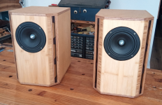
Ended up with about 19L internal volume, give or take, with six 8x1cm ports of approx 21cm length (ending about 5cm from the back of the inside of the enclosure and accounting for the length lost cutting the front chamfers). Front panels are IKEA bamboo 'butcher block' chopping boards (3cm thick) as I couldn't find decently priced bamboo ply in Australia, everything else is cheap 12mm 'hardwood' plywood (appears to be mostly pine with thin hardwood veneer). Decided to go down the BBC/Harbeth-style 'lossy' internal damping path instead of doing bracing like Dave recommends (primarily out of laziness) so a couple of layers of automotive butyl damping material on the sides/top/bottom, and a bunch of felt, foam, and melamine sponges on the front and back panels. The melamine worked really well in some Karlson-style enclosures I built recently - thanks to xrk971 for that idea!
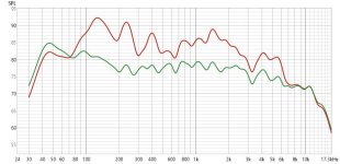
I've attached a couple of frequency response plots (from REW with 'psychoacoustic' smoothing) - the red line is the original response and the green is after I equalised it to approximately a Harman curve as a very coarse initial test. I believe a lot of the variability in the original response is room-related as they are in a very suboptimal location - near ceiling height on a floating shelf, not far from room corners, in a long and narrow kitchen full of irregular hard surfaces with one side almost entirely glass). I had plenty more SPL than I needed so sacrificed a fair few decibels to get a flatter response. The treble dropping off a cliff after 10k is something that I knew was coming given the drivers used and which surprisingly isn't all that audible to me when compared to other speakers I've built that don't roll off as quickly.
Anyway, hope this helps anyone who might want to try a similar thing with this driver in future. Can definitely recommend!
Ended up with about 19L internal volume, give or take, with six 8x1cm ports of approx 21cm length (ending about 5cm from the back of the inside of the enclosure and accounting for the length lost cutting the front chamfers). Front panels are IKEA bamboo 'butcher block' chopping boards (3cm thick) as I couldn't find decently priced bamboo ply in Australia, everything else is cheap 12mm 'hardwood' plywood (appears to be mostly pine with thin hardwood veneer). Decided to go down the BBC/Harbeth-style 'lossy' internal damping path instead of doing bracing like Dave recommends (primarily out of laziness) so a couple of layers of automotive butyl damping material on the sides/top/bottom, and a bunch of felt, foam, and melamine sponges on the front and back panels. The melamine worked really well in some Karlson-style enclosures I built recently - thanks to xrk971 for that idea!
I've attached a couple of frequency response plots (from REW with 'psychoacoustic' smoothing) - the red line is the original response and the green is after I equalised it to approximately a Harman curve as a very coarse initial test. I believe a lot of the variability in the original response is room-related as they are in a very suboptimal location - near ceiling height on a floating shelf, not far from room corners, in a long and narrow kitchen full of irregular hard surfaces with one side almost entirely glass). I had plenty more SPL than I needed so sacrificed a fair few decibels to get a flatter response. The treble dropping off a cliff after 10k is something that I knew was coming given the drivers used and which surprisingly isn't all that audible to me when compared to other speakers I've built that don't roll off as quickly.
Anyway, hope this helps anyone who might want to try a similar thing with this driver in future. Can definitely recommend!
Attachments
I have used WinISD. The program allows using multiple slots. However, I don't know if it works to simulate Onken or miniOnken.
Can imagine that it is more advanced equation. But it's a nice program to play with.
Hornresp is more advanced. Powerful and more possibilities to simulate basically all types of boxes with or without damping inside.
Hornresp can give a fairly accurate picture of a frequency curve that you can trust depending on the room you place the speakers in. Everything affects the frequency curve in a room.
Calculate the summed pipes' end correction air mass 'bubble', otherwise you're in effect horn loading them, which is what most can make 'guessing' an exercise in futility'.Also, on that note, is there any general rule about the minimum distance from the back the vents / inner side wall should start?


FWIW, in my studies the pioneers were strictly about max SPL@highest possible speech intelligibility/available power, hence strictly Fb = Fs due to the drivers having basically zero Xmax; using variable damping (DF) tone controls for impedance matching, which in turn dictated effective Sd = Av, allowing increasing design flexibility with increasing Xmax and/or power.As I said above, Onkens indirectly descend from the Jensen Ultraflex which itself descends from the traditional pre-T/S bass reflex enclosure. These were very different to 'modern' types of vented box, with maximum efficiency at Fb being a [read 'the'] baseline goal, which typically required Av [vent CSA] to be equal, or very close to Sd. Whether you actually wanted / needed that as-is was another question, but the pioneers took it as read that designers & builders would damp out what they didn't need, on the principle that it's better to have too much than too little -when you have too much you can always do something about it.
- Home
- Loudspeakers
- Full Range
- Help with tuning Onken enclosures