Hello everyone,
I am in the process of finding parts to build Tortello's headphone amp http://www.diyaudio.com/forums/showthread.php?s=&threadid=2451&pagenumber=1 and have a few questions I hope some one can help me with. (By the way i have never built an amp before so be gentile with me 😉 ).
1. The transformer. what VA and secondary voltage is recommended for this design?
I found an 80VA 2x25 toroidal at www.maplin.co.uk stock No.vs24b, would this be suitable?
2. I have not been able to find anywhere (maplins, farnell and RS) the zener diodes that are on the schematic which Tortello sent me, could some one recommend suitable a replacement?
3. even more basic question now, sorry.
On the schematic some of the caps have one straight side with a + next to it and the other plate is curved, while some (actually only 1, C2) have both plates straight. what is the difference?
I know that there are many different types of caps all made from different materials, what type would you recommend for sound quality (However i am on a budget, sadly😡 )
4. The Bias and Bal pots, are these trim pots?
OK I think that will do for now, I hope someone can help
Thankyou,
Kram
🙂 🙂
A transformer at 80va rating is very good .I build mine with the same amount.
But use the secondaries in parallel for 0-25 volt.
At the results you will get around 35 volts on the unregulated supply.Just fine.
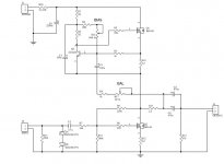
If you want to trim R15 (180k) - I refer to the schematic at page 1 of the thread- do it ! With a voltmeter measure set the drain of Q2 at half of the supply vaule.
On the schematic I see 5 polarized caps, they are:
C1,C2 power supply filtering;
C3,C4, current source;
C5 output cap.
It is not necessary go for exotic parts .
Ah, the diodes.Sure they are there back to back for input protection.The voltage rating of these zeners are from ,say 9 volts to 18 volts .
Cheers
But use the secondaries in parallel for 0-25 volt.
At the results you will get around 35 volts on the unregulated supply.Just fine.
If you want to trim R15 (180k) - I refer to the schematic at page 1 of the thread- do it ! With a voltmeter measure set the drain of Q2 at half of the supply vaule.
On the schematic I see 5 polarized caps, they are:
C1,C2 power supply filtering;
C3,C4, current source;
C5 output cap.
It is not necessary go for exotic parts .
Ah, the diodes.Sure they are there back to back for input protection.The voltage rating of these zeners are from ,say 9 volts to 18 volts .
Cheers
The ones with the + signs are polarized, or electrolytic, types. In order to cram more energy storage into a small package it becomes necessary that the capacitor voltage be applied only one way. There are some nonpolarized electrolytics but they are quite rare. Use aluminum electrolytics, not tantalum.Kram said:
On the schematic some of the caps have one straight side with a + next to it and the other plate is curved, while some (actually only 1, C2) have both plates straight. what is the difference?
Thanks for the swift replies.
stefanobilliani, so any zener with a voltage rating of between 9v and 18v would be good?
I am wanting to build this amp in a similar way to the one Tortello has done in the pictures he posted of one he completed, by that i mean with a preamp in the same box.
Would anyone know where i could get a schematic of the other parts of the amp he built or something similar? Well I could always ask Tortello anyway.
Thanks
Kram.
Hello,
I've just seen this thread, and all the replies seem to me correct.
The definitive schematic is slightly different from that was published in this forum, mainly in the power supply stage, and if you post here a request, I can email the main PCB stuff immediately, in case you haven't ever done.
As soon as possible Cmoy, from Headwize.com, will publish the whole project, included the power supply and the timer/h.f. equalizer (heresy!? Not for me, I have a Grado SR325...) stages.
The transformer should be at least 30VA rated, I use an high quality Talema 2x18V/50VA with good results.
If you build a dual mono power supply, you may join the GND rails (one for each channel) in only one point - the common ground of the headphone connector. This point can be wired to the metal chassis.
C5 and C4 should be good quality capacitors, an yes, no tantalum: the difference is quite notable.
Hope this helps.
Marcello
Hi Tortello, you did send me a schematic a while ago, it can be seen below.
there is one question i forgot to ask about the caps, what voltage rating should they be?
Thank you Tortello for sending me the schematic in the first place and i hope mine turns out at least half as good as yours.
Thanks🙂
there is one question i forgot to ask about the caps, what voltage rating should they be?
Thank you Tortello for sending me the schematic in the first place and i hope mine turns out at least half as good as yours.
Thanks🙂
Attachments
Hi Kram,
it depends on the transformer voltage rating, since the circuit is not critical towards power supply values.
If you decide to follow the values recommended -18Vac for the P.T.- the power supply capacitors voltage ratings should be at least 35WV. C1, C3, C4 and C5 breakout voltage could be lower, but my advise is to put there 35V capacitors too, given that the price difference is marginal.
Let's consider that C4 and C5 resolve the B+/2 component (about +12Vdc) from your headphone coils.
I hope you'll enjoy with this circuit.
Best Regards
Marcello
... and if you use a 25V transformer, the capacitor rating must be 50WV.
As Stefano wrote, in this case you need to trim the +B/2 at Q2 drain, to achieve the maximum voltage modulation.
Cheers
Marcello
As Stefano wrote, in this case you need to trim the +B/2 at Q2 drain, to achieve the maximum voltage modulation.
Cheers
Marcello
IRF610
How many IRF610's would you recomend I buy to get some that match, i am planning on building 2 amps.
Do you think 25 will be enough?? or is that too many??
any help appreciated
Thanks Kram.
How many IRF610's would you recomend I buy to get some that match, i am planning on building 2 amps.
Do you think 25 will be enough?? or is that too many??
any help appreciated
Thanks Kram.
Buy 10-15 of them.
The rest of them will be good to
have and use in other projects.
How many, it depends somewhat how much money you have, and
how much you need for everything else in your life.
Like rent, food, clothes, movies, CD-recordings
and for to spend on the person you love.
The rest of them will be good to
have and use in other projects.
How many, it depends somewhat how much money you have, and
how much you need for everything else in your life.
Like rent, food, clothes, movies, CD-recordings
and for to spend on the person you love.
Sorry but i have another basic question.
I am about to place an order for the parts i need and i would like to know if there are any types of resistor I should avoid using i.e ones that would make my amp sound bad?
thank you all for your help so far.
Kram.🙂
I am about to place an order for the parts i need and i would like to know if there are any types of resistor I should avoid using i.e ones that would make my amp sound bad?
thank you all for your help so far.
Kram.🙂
What does the article say of RESISTORS
at the Headwize site?
Tortello HeadPhone Amplifier Project Homepage
Kram,
I would start a new Thread about this
at the HeadWize Forum!!!!!! 😉
Doesn't the construction article mention the type of resistorsKram said:I am about to place an order for the parts i need and i would like to know if there are any types of resistor I should avoid using i.e ones that would make my amp sound bad?
thank you all for your help so far.
Kram.🙂
at the Headwize site?
Tortello HeadPhone Amplifier Project Homepage
Kram,
I would start a new Thread about this
at the HeadWize Forum!!!!!! 😉
Hello,
Refering to the schematic of the amp found here
http://headwize2.powerpill.org/projects/showproj.php?file=pellerano_prj.htm
does C2 have to be non-polarised or will a normal polarised electrolytic cap suffice?
In case anyone is interested i am planning on using general purpose +-1% metal film 0.5W resistors from RS for the all resistors other than the ones that require a higher W rating. Anything wrong with this?
Thank you.🙂
Hello Kram, hello all,
C2 should be a polyester (or other plastic dielectric) type.
Normal metal film resistor type will be perfect.
Cheers
Marcello
C2 should be a polyester (or other plastic dielectric) type.
Normal metal film resistor type will be perfect.
Cheers
Marcello
a bit of trouble.
Hello,
I am having difficulty setting the balance trimmer (R17). I have followed the instrustions on headwize and I am not getting any waveform on my scope when i measure accross R10. when i measure accross R12 i do get a sine wave but it is a little distorted, the +ve peak of it is more pointy than the -ve peak (if you catch my drift).
Just to let you all know, I am using a 2x 18V transformer and not what i stated earlier. also my circuit is not on a pcb but on strip board. I can post a scan of my strip board design when i get to work tomorrow if it will help anyone diagnose my problems.
Also I could not get hold of any 20k resistors for R4 so I have used a 22k instead. I do not know if that would have any huge effect on the amps opperation or not.
thank you all for your help,
Kram.
🙂
Hello Kram,
the R4 value is not so important (there is a trimmer in series).
Do you have checked the bias current through R10/R12?
Marcello
the R4 value is not so important (there is a trimmer in series).
Do you have checked the bias current through R10/R12?
Marcello
Hello,
I am still having a few problems with the only channel I have built so far.
The Volume pot (Alps 20k, RS part number 263-3258) seems to have little effect on the volume. When I connect the amp up to my MD player (not a portable) which out puts about 1.5V the volume in the head phones (sennheiser HD590) is far too loud.
I think I probably have the pot wired up wrong, the input from the rca socket is connected to pin3 and the output to the amp is connected accross pins 1 and 2, is this wrong/right?
The cap I have used for C2 is a 4.7uF EVOX MMK 63- (RS number 298-0217), is this good to use or should i get something else instead?
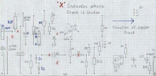
Here is my stripboard layout. Can anyone see if it does not match the circuit diagram on the headwize site? J1 is supposed to say +24V and J2 is the input.
Thank you,
Kram
🙂
I am still having a few problems with the only channel I have built so far.
The Volume pot (Alps 20k, RS part number 263-3258) seems to have little effect on the volume. When I connect the amp up to my MD player (not a portable) which out puts about 1.5V the volume in the head phones (sennheiser HD590) is far too loud.
I think I probably have the pot wired up wrong, the input from the rca socket is connected to pin3 and the output to the amp is connected accross pins 1 and 2, is this wrong/right?
The cap I have used for C2 is a 4.7uF EVOX MMK 63- (RS number 298-0217), is this good to use or should i get something else instead?
Here is my stripboard layout. Can anyone see if it does not match the circuit diagram on the headwize site? J1 is supposed to say +24V and J2 is the input.
Thank you,
Kram
🙂
Attachments
Hello,
Volume pot: if you put the signal to pin #3, the pin 1 should be connected to ground, and pin 2 to the input of the amplifier.
It's very difficult to understand the wiring plan without the copper side.
What about the bias, with no signal applied?
Why don't you print the overlay layout, apply the sheet on the pcb (or other insulating material) to drill the holes as the "original" layout, and make the connections according the bottom layout?
This should be easier...
Marcello
Bias current through R12 (0.462V/2.2R) is 211mA.
Quiescent voltages:
Q1, D=23.8, G=16.35, S=11.75
Q2, D=11.29, G=5.05, S=0.46
Just so you know, my headphones impedance is 120ohms.
I have used Track strip/strip board/verro board to build my amp on, I do not have the facilites to make PCBs 🙁 .
This track strip (or whatever you want to call it) has parallel horizontal copper tracks on the bottom. The horizontal lines on the graph paper my diagram is on represent the copper tracks (like the blue arrow shows). Where every vertical and horizontal line cross on the graph paper corresponds to a hole in the board where the leads of the complnents fit through and are then solderd to the copper strip.
I am sure someone will know what i am talking about.
Any way, thanks for telling me how to wire up the pot correctly, it now sounds much much better, the sound lacks bass though. I am hoping it will get better the more i use it. 🙂
thankyou
Kram
- Status
- Not open for further replies.
- Home
- Amplifiers
- Headphone Systems
- Help with Tortello's headphone amp.