Hello Kram,
did you miss a cross on the right of R17?
In this case there should be an error (the trimmer bypasses the C4, C5 capacitor bank...)
This is the first thing I've seen, as soon as possible I'll try to decode your circuit.
Marcello
did you miss a cross on the right of R17?
In this case there should be an error (the trimmer bypasses the C4, C5 capacitor bank...)
This is the first thing I've seen, as soon as possible I'll try to decode your circuit.
Marcello
You are right, I forgot to draw that cross on the diagram, all though I did actually have that track cut on my circuit board.
thank you.
Kram🙂
thank you.
Kram🙂
Layout looks ok
Kram,
I do not see any mismatch between your layout and the circuit given at :-
http://headwize2.powerpill.org/projects/showproj.php?file=pellerano_prj.htm
Do you have it working now ?
Dave
Kram,
I do not see any mismatch between your layout and the circuit given at :-
http://headwize2.powerpill.org/projects/showproj.php?file=pellerano_prj.htm
Do you have it working now ?
Dave
I have it working now, I am building the 2nd channel as I type. Thanks to both of you for going over the circuit for me, I just needed a second opinion.
Thank you
Kram
Thank you
Kram
Hello all,
I have now built the second channel and surprise surprise it dosent work. I am getting dc on the out put (151mV).
Some measurements.
Quiesent voltage accross R12 = 0.462V
Q3: collector voltage (measured wrt ground) = 80.4V (yes thats right)
Base V =5.85V
Emitter V = 5.65V
Q1: G = 10.48V
D = 24.4V
S = 27V
Q2: G = 5.33V
D = 5.55V
S = 0.53V
Something is obviously wrong but I dont know what it is.
I have replaced Q3 once already and it made no difference. I have checked the circuit many times for solder bridges and parts being in the wrong place, the circuit is exactly the same as the first channel.
Does anyone have an idea what has gone wrong?
A bad FET or something?
Help!!
Thank you
Kram.
Unintentiona loscillator ??
Kram,
 80.4V ?
Where does this come from !!
Assuming we are looking at the same circuit diagram ....
Your figure accross R12 looks good, I would expect to see something
similar dropped accross R10 - but from your other figures
(Q1-S to Q2-D) give 27 - 5.55=21.45V giving 9.75 A !
Only 200W of power !
I think you may have inadvertently built an RF oscillator -
this may explain the crazy readings.
Do you have a scope ?
What voltage reading do you get directly accross R10 ?
Check Q1-S , Q3-C on and ac range.
Dave
Q3: collector voltage (measured wrt ground) = 80.4V (yes thats right)
Base V =5.85V
Emitter V = 5.65V
Kram,
80.4V ? Where does this come from !!
Assuming we are looking at the same circuit diagram ....
Your figure accross R12 looks good, I would expect to see something
similar dropped accross R10 - but from your other figures
(Q1-S to Q2-D) give 27 - 5.55=21.45V giving 9.75 A !
Only 200W of power !
I think you may have inadvertently built an RF oscillator -
this may explain the crazy readings.
Do you have a scope ?
What voltage reading do you get directly accross R10 ?
Check Q1-S , Q3-C on and ac range.
Dave
I dont have a scope at home but i have one at work i can use.
the voltage directly across R10 is 0.463V.
All the measurements were taken with no signal at the input, (i dont dare connect anything to it at the moment).
and yes my multimeter still says 80.4V Q3 C
another thing that might help, Q1 heatsink gets hot (no hotter than Q1 on the channel that works though) while Q2's sink is hardly luke warm.
thanks for the help, i need it.
Kram
Bias looks OK then ...
Kram,
I am no expert on this circuit, but it seems to me that it must be oscillating.
Maybe you should verify this with a 'scope.
Do you have any load connected ?
 Assuming it's oscillating, then it may be due to parasitic capasitance around Q1.
I notice from your layout Q1 is rather remote from R5 - this is not good as the
parellel tracks between Q1-G -> Q1-D -> Q1-S form a small capasitor.
If this is the case try relocating Q1 closer to R5 and cut the track either side of the
junction of R5 and Q1-G. Do the same with the track around the junction of
R6 and Q2-G
Good luck,
Dave
Kram,
I am no expert on this circuit, but it seems to me that it must be oscillating.
Maybe you should verify this with a 'scope.
Do you have any load connected ?
Assuming it's oscillating, then it may be due to parasitic capasitance around Q1.I notice from your layout Q1 is rather remote from R5 - this is not good as the
parellel tracks between Q1-G -> Q1-D -> Q1-S form a small capasitor.
If this is the case try relocating Q1 closer to R5 and cut the track either side of the
junction of R5 and Q1-G. Do the same with the track around the junction of
R6 and Q2-G
Good luck,
Dave
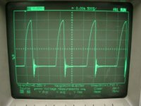
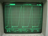
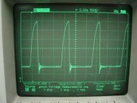
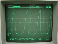
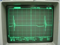
Here are some pics of measurements taken with a scope.
I tried moving Q1 and it had no effect, I also replaced Q1, Q2 and Q3 with new ones and i still got the same results. I have also replaced as many of the passive components as i could and still it had no effect. I then rebuilt the entire circuit on a fresh piece of board and i still get the same results.
Whats going on???
This is the output.
Attachments

Kram,
Try a small capacitor across Q3 collector to base .001 uf. See if that stops the oscillation. You posted a value of 80 volts on Q3 ?? but on your scope postings I dont see that value.
BDP
Try a small capacitor across Q3 collector to base .001 uf. See if that stops the oscillation. You posted a value of 80 volts on Q3 ?? but on your scope postings I dont see that value.
BDP
I forgot to mention about that reading at Q3C, when i use my meter (a mastech MAS-343) i get that 80V reading, however at work I used 2 different meters and the scope and i got a reading of some 6V ish i think it was. it definatley wasnt 80 though. something weird going on with my meter i think🙁
thank you
Kram
thank you
Kram
Mmmmmm ....
Kram,
I wish I could be more help, but, in case it's useful :
Some comments
[1] Is there an input signal applied, if so what is it ?
[2] What is the output load ?
[3] What is the sweep speed (timebase, secs / div)
[4] Q3 appears to be doing its job from c-b-e measurements !
(wierd signals though)
[5] Q1D looks strange - thats a 12V swing on the +24 rail ?
(can't see the voltage measurements - guessing swing between 12V-24V)
(this can't be right !)
[6] Q1S is showing some nasty ringing - also it should be centered around
12V but it is showing Vavg 23V
(have you mislabeled QID & Q1S measurements ?)
Suggestions
[a] Can you superimpose input signal on measurements (if there is one) ?
Measure accross R10, R12 & R18. They should all look similar.
Dave
Strange meter readings
Kram,
The strange meter readings can occur when there is a significant HF/RF component in the signal being measured. DVM's are particularly prone to this but antique instruments like an AVO Mk8 are much more immune (I learnt this at the side of a master "old school" RF engineer many years ago, along with the many other strange effects induced by bonbarding equipment with upto 1GHz at 10V/M 😀 😀).
Dave
Hello DRC,
you are being helpfull and I am very thankfull for your replies.
There is no input signal applied.
When there is no input applied to the input of the channel that works I dont get any funny readings from it.
There is no load on the output.
When there is no load on the output of the channel that works i dont get any funny readings either.
I will try your suggestions when i get home tonight and make some measurements.
Thanks for you time
Kram
- Status
- Not open for further replies.
- Home
- Amplifiers
- Headphone Systems
- Help with Tortello's headphone amp.