salas said:
Happy new year from me and happy listening! I am quite impressed by your bold take in creating your very own amp and having proceeded so long. Bravo.
Happy new year to you too Salas!
Thanks. It would be a lie for me to say that I'm not impressed by this amps performance. 😀
This has been like an obsession for me over the past three months. It has payed off in the end, as I have bettered what I set out to do. Lots of help from members here, especially Pete (PB2) is much appreciated.
It's been a while. I have been busy with other pursuits.
I have the final board layout plus pdf's to follow for those interested in making their own boards (very rewarding).
A possibility (no, a certainty) looms on the horizon for actual testing of this amp with a real distortion analyzer. I'll post those results when I have them.
Without further ado:
I have the final board layout plus pdf's to follow for those interested in making their own boards (very rewarding).
A possibility (no, a certainty) looms on the horizon for actual testing of this amp with a real distortion analyzer. I'll post those results when I have them.
Without further ado:
Attachments

I'm impressed and overhelmed with enthusiasm
Hello MJL21193
I recogniced myself in you at the very first post and when the replys popped in on your fine project. I have maybe more electronics knowledge (school) from the begining but you really impressed me with your learning curve of autumn of 2007. 😉
I'm very very impressed of this thread. I'm a lurker at this forum, have always been. It's also not easy to break trough and get attention here. And also to send PM's before you've been moderated for ... apparently some time (?)
I have read this thread all trough once, but now I'm doing it all over again, using the same simulate software as you.
So, I also have the National Instruments Circuit Design Suite, Multisim 10. It's easy to use and I have recently followed your project from page 2 to post# 152 where you finally use MJL3281A and MJL1302A as output devices. 🙂
I'm concerned though, that I never got any decent working simulation before changing R5 down to 220 ohm. (some pages ago) Then i was able to have a load at 8 ohm without severe oscillating.
I also tried to use "On semis" models of MJL4281A and MJL4302A but I always get an error from the simulator about the netlist. When I have clicked the confirmationboxes the simulation works OK as it seems (?)
Did I miss someting on that models and also, have you done the model "wizard" for them, yourself?
At post #152 you use the BJT's that I also have in my master library but as it is now I now have a clipping at the negative rail before the positive, that I dont like.
I would be glad for any comment or thoughts about this.
My goal is to, maybe, use your design with the new TherlmalTrak devices from On Semi. But I have to be in the "ballpark" with your allready done simulation before anything is changed.
What PSU do you use in your part of the simulation? Do you care to share your simulation files with me?
And also, besides I have to redo the PCB work because of the above named devices, I don't like your PCB layout (no offence 🙂 ) and I will do my own because I can... We have an etch tank at my work, with all equipment, and I just love singlesided PCB's of my own 😀
At last, what impressed me most was your oscilloscope pictures of the amp running with 2uF capacitor as load. don' remember was it 10kHz SQW? That is the ultimate test. Some ringing is OK as long as the amp doesn't oscillate ... or burn 😎
Re: I'm impressed and overhelmed with enthusiasm
Hi Radioman62,
I'm sorry, I missed your post.
The latest schematic (on this page, post #582) is the one I'm working with on my prototype. It has all of the correct components and runs completely stable.
The models for the output devices are from andy_c. He improved the MJL3281A/1302A models. With that said, I have the MJL4281A/4302A in my prototype and these perform very well.
I can email the sim file to you, as soon as I find the right one. Saved each time I made a change - some 35 or more revisions. One problem will be that you will not have a few of the models I have modified and saved in the user database. I see about packing those in with the sim file.
For the bulk of the simulation, I used DC power supplies set to +/-56 volts. This speeds up the process.
As for the board layout, you may do as you wish. I can say that the time and effort and advise that went into the board layout paid off - it works beautifully. No noise, relatively compact and well proportioned.
If you make another layout, I'd like to see it. You could post it here.
Finally, good luck. From everything I've seen so far, this amp is well worth building.
The prototype will be subjected to some tests tomorrow (with real equipment 🙂 ).
For better or worse, I'll post the results soon.
Radioman62 said:
I'm concerned though, that I never got any decent working simulation before changing R5 down to 220 ohm. (some pages ago) Then i was able to have a load at 8 ohm without severe oscillating.
I also tried to use "On semis" models of MJL4281A and MJL4302A but I always get an error from the simulator about the netlist.
At post #152 you use the BJT's that I also have in my master library but as it is now I now have a clipping at the negative rail before the positive, that I dont like.
I would be glad for any comment or thoughts about this.
My goal is to, maybe, use your design with the new TherlmalTrak devices from On Semi. But I have to be in the "ballpark" with your allready done simulation before anything is changed.
What PSU do you use in your part of the simulation? Do you care to share your simulation files with me?
And also, besides I have to redo the PCB work because of the above named devices, I don't like your PCB layout (no offence 🙂 ) and I will do my own because I can... We have an etch tank at my work, with all equipment, and I just love singlesided PCB's of my own 😀
At last, what impressed me most was your oscilloscope pictures of the amp running with 2uF capacitor as load. don' remember was it 10kHz SQW? That is the ultimate test. Some ringing is OK as long as the amp doesn't oscillate ... or burn 😎
Hi Radioman62,
I'm sorry, I missed your post.
The latest schematic (on this page, post #582) is the one I'm working with on my prototype. It has all of the correct components and runs completely stable.
The models for the output devices are from andy_c. He improved the MJL3281A/1302A models. With that said, I have the MJL4281A/4302A in my prototype and these perform very well.
I can email the sim file to you, as soon as I find the right one. Saved each time I made a change - some 35 or more revisions. One problem will be that you will not have a few of the models I have modified and saved in the user database. I see about packing those in with the sim file.
For the bulk of the simulation, I used DC power supplies set to +/-56 volts. This speeds up the process.
As for the board layout, you may do as you wish. I can say that the time and effort and advise that went into the board layout paid off - it works beautifully. No noise, relatively compact and well proportioned.
If you make another layout, I'd like to see it. You could post it here.
Finally, good luck. From everything I've seen so far, this amp is well worth building.
The prototype will be subjected to some tests tomorrow (with real equipment 🙂 ).
For better or worse, I'll post the results soon.
Hi John,
I've been meaning to suggest that you try adding the bootstrap resistor to the diff amp cascodes in the real hardware to see if you get the expected reduction in distortion. It should be more effective just below clipping. As I recall, you removed it based on simulation results and I don't think that they're accurate, it should reduce the distortion.
Pete B.
PB2 said:Hi John,
I've been meaning to suggest that you try adding the bootstrap resistor to the diff amp cascodes in the real hardware to see if you get the expected reduction in distortion. It should be more effective just below clipping. As I recall, you removed it based on simulation results and I don't think that they're accurate, it should reduce the distortion.
Pete B.
Hi Pete,
I haven't touched this amp for almost a month. I guess I got burned out on it - too many hours devoted to it.
I'll be taking it on the road tomorrow to have some measurements taken, notably for distortion. Armed with that, I can decide where I want to go.
The simulation was my master, lulling me with reductions of .oo1% or so, most of the time these were due to no real improvement, but just a different number to show me.
I will get back to it again and try some more changes, including the bootstrap to the input cascode. I really didn't give it a fair try.The prototype still has all of the traces for routing this.
Re: Re: I'm impressed and overhelmed with enthusiasm
It's OK. For a moment i thought I was invisible though. Non of my first three posts at this forum got any answer 🙂
🙂
If it's to much hassle just send me the simulation. I maybe can change some of the models to ones that I have.
Should be enough to decrease the resistor values to get the same currents, or maybe there is more to it?
Please do, we all looking forward. Take care though. We do not need any "burned out" amp-designer 😀
MJL21193 said:
Hi Radioman62,
I'm sorry, I missed your post.
It's OK. For a moment i thought I was invisible though. Non of my first three posts at this forum got any answer
🙂 I can email the sim file to you, as soon as I find the right one. Saved each time I made a change - some 35 or more revisions. One problem will be that you will not have a few of the models I have modified and saved in the user database. I see about packing those in with the sim file.
If it's to much hassle just send me the simulation. I maybe can change some of the models to ones that I have.
Same as me. But I would like to drive this amp with less Voltage, because I allready have two 200VA transformers which gives about +/-41 to 45 volts DC (fully loaded and unloaded)For the bulk of the simulation, I used DC power supplies set to +/-56 volts. This speeds up the process.
Should be enough to decrease the resistor values to get the same currents, or maybe there is more to it?
The prototype will be subjected to some tests tomorrow (with real equipment 🙂 ).
For better or worse, I'll post the results soon.
Please do, we all looking forward. Take care though. We do not need any "burned out" amp-designer 😀
Very nice Cougar restoration there Radioman, I'm not a fan of Fords but I do like the Windsor motor. The car and motor look fantastic!
Pete B.
Pete B.
Re: Re: Re: I'm impressed and overhelmed with enthusiasm
Hi Radioman,
Sent me your email address and I'll give you the sim file. I've changed the models to ones from the master database.
To use less voltage just change the gain to adjust the input sensitivity. R31 and possibly R34.
Radioman62 said:
If it's to much hassle just send me the simulation. I maybe can change some of the models to ones that I have.
Same as me. But I would like to drive this amp with less Voltage, because I allready have two 200VA transformers which gives about +/-41 to 45 volts DC (fully loaded and unloaded)
Should be enough to decrease the resistor values to get the same currents, or maybe there is more to it?
Hi Radioman,
Sent me your email address and I'll give you the sim file. I've changed the models to ones from the master database.
To use less voltage just change the gain to adjust the input sensitivity. R31 and possibly R34.
Hello Pete
It's not a simple windsor engine. It's the legendary Cleveland 351cui under the hood in my cat. 😎
It's not a simple windsor engine. It's the legendary Cleveland 351cui under the hood in my cat. 😎
Ot
Sorry, yes I meant to say Cleveland, flipped the two as its been a while, the one with the canted valves for better flow. Also used in the Detomaso Pantera. Nice!
Pete B.
Radioman62 said:Hello Pete
It's not a simple windsor engine. It's the legendary Cleveland 351cui under the hood in my cat. 😎
Sorry, yes I meant to say Cleveland, flipped the two as its been a while, the one with the canted valves for better flow. Also used in the Detomaso Pantera. Nice!
Pete B.
Wasn't the Windsor just a 302 with a longer stroke crank? Same bore IIRC. Or was that the other way around? My love of cars lives on but my interest in the mechanics has wained.
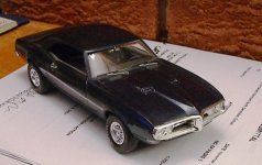
Still, I'd love to have the spare time (and space) to do a resoration. Maybe one of my favourites - 1968 Firebird.
Alas, I'm afraid this might be as close as I'll get:
Still, I'd love to have the spare time (and space) to do a resoration. Maybe one of my favourites - 1968 Firebird.
Alas, I'm afraid this might be as close as I'll get:
Attachments
Test results...
Ok, I went to Chris' (Anatech) today and brought the prototype for some basic testing. A very pleasant afternoon Chris, thanks for taking the time. 🙂
Chris has an HP 339A distortion analyzer and we were looking at the residual on a very smart looking USB connected PC scope with a lot of features. I might have to get one of those.
Basically, the results pretty much back up what RMAA said: distortion at full power comes in at 0.006%.
Full power into an 8 ohm load is ~130 watts.
Amp is stable and well behaved.
MJL21193 said:
The prototype will be subjected to some tests tomorrow (with real equipment 🙂 ).
For better or worse, I'll post the results soon.
Ok, I went to Chris' (Anatech) today and brought the prototype for some basic testing. A very pleasant afternoon Chris, thanks for taking the time. 🙂
Chris has an HP 339A distortion analyzer and we were looking at the residual on a very smart looking USB connected PC scope with a lot of features. I might have to get one of those.
Basically, the results pretty much back up what RMAA said: distortion at full power comes in at 0.006%.
Full power into an 8 ohm load is ~130 watts.
Amp is stable and well behaved.
The Windsor had inline valves like most V8s whereas the Cleveland had canted valves for better flow. Radioman62's picture:
http://www.binatech.se/hem/Cougar/2vheads_boltonready.jpg
My family had a 1967 Firebird and I agree the styling really is timeless. It really was a pony car as the handling didn't improve significantly until the Trans Am.
Pete B.
http://www.binatech.se/hem/Cougar/2vheads_boltonready.jpg
My family had a 1967 Firebird and I agree the styling really is timeless. It really was a pony car as the handling didn't improve significantly until the Trans Am.
Pete B.
- Status
- Not open for further replies.
- Home
- Amplifiers
- Solid State
- Help with this amp? A patchwork product of simulation