Try R2, R3 = 50-100 ohms.
Do you have HF bypass caps in place?
I usually turn the bias down, and provide current limiting
when running off the full supply voltage and check if
bias points look right. Then, up the current limit.
Did something else fail perhaps?
I'll be in and out today, will try to help.
Pete B.
Do you have HF bypass caps in place?
I usually turn the bias down, and provide current limiting
when running off the full supply voltage and check if
bias points look right. Then, up the current limit.
Did something else fail perhaps?
I'll be in and out today, will try to help.
Pete B.
Hi Pete,
I'll switch R2,R3. Bypass caps are in place (though no decoupling caps) behind heatsink, close to the output transistors.
As for something failing, I'm confused, since it works on the lower voltage. Wouldn't it exhibit the same behavior on the lower supply?
I've been working on a more permanent bench power supply, that will have a +/-18 volt @ 2A. I will try it on this supply.
MJL21193 said:Hi Pete,
I'll switch R2,R3. Bypass caps are in place (though no decoupling caps) behind heatsink, close to the output transistors.
As for something failing, I'm confused, since it works on the lower voltage. Wouldn't it exhibit the same behavior on the lower supply?
I've been working on a more permanent bench power supply, that will have a +/-18 volt @ 2A. I will try it on this supply.
The resistive emitter load on the diff pair makes the bias current proportional to supply voltage. Most amps will work over a wide range but it depends on the design. I'm thinking that the mirror is running out of voltage headroom.
It would be good to at least roughly duplicate the planned grounding. I understand that you're just trying to prove out the basic circuit, however it would also be good to roughly prove out the layout, even if you hang the PS caps off the side or bottom. You can test for hum at some point by placing the cicuit close to the PSU bridge.
Pete B.
PB2 said:
I'm thinking that the mirror is running out of voltage headroom.
It would be good to at least roughly duplicate the planned grounding. I understand that you're just trying to prove out the basic circuit, however it would also be good to roughly prove out the layout, even if you hang the PS caps off the side or bottom. You can test for hum at some point by placing the cicuit close to the PSU bridge.
Hi Pete,
That is indeed the case. I finished the 18 volt supply and ran it on that, after changing R2 and R3. Then I tried the +/- 35 volt supply. It ran no problem.
I then undid the other things that I did, except for the two pole compensation. I'll get to that next.
I must say, apart from that minor glitch, I'm very impressed with how it's turned out.
After I do some more testing on this prototype, such as running it at full supply, I'll redo the whole thing on a bigger perf board according to the layout. Power supply and all.
On a side note, I'm astounded that there hasn't been more interest in this project. The fact that I can ask for some help and get none, except from the biggest contributor (other than myself), is remarkable. All of the knowledge out there, seemingly going to waste, talking about trivia and old hat issues.
Best defines "do it yourself"
Thanks Pete, you've be a true friend here.
🙂
Thanks so much John,
I enjoy both the theory and building, but have not had the time to build lately so this has been an excellent thread to at least see your design come alive. It's also motivated me to do more simulations on the power amp I've been working on.
Your doing an excellent job for a guy who down plays his skills so much, LOL! I like your style, a nice mix of theory with a goal to build something with some new features.
Do you plan to do square wave tests into a dummy 8 ohm load?
Then with some capacitance as a test of the stability?
I think you mentioned a scope, do you have a function generator?
Once again, nice job!
PB2 said:
Do you plan to do square wave tests into a dummy 8 ohm load?
Then with some capacitance as a test of the stability?
I think you mentioned a scope, do you have a function generator?
I don't have a function generator, but in my "lab" I have a computer with a dent sound card. Although it's not nearly as precise, I'll use this with a software generator.
I have a Tektronix 2465BCT scope and a 1X/10X probe
Obviously, I'm not going to be able to do any really sophisticated testing. I would like to test the distortion though.
It's going to be a while before I commit this to it's final pc board. I'd like to make sure I have all of the bugs worked out.
Without your help Pete, the amp would have wound up looking (and behaving) like a hundred others out there - just a re-hash of the same old same old.
Thanks again.
MJL21193 said:
I have a problem. It appears Q4 (VAS) is saturated.
PB2 said:Try R2, R3 = 50-100 ohms.
Well, even though it was running fine, it still didn't seem right. The voltages in the input stage didn't match the sim very well. When I connected the full rail voltage (+/-56V), I saw BIG voltages and felt HEAT coming from the input stage. I came close to unleashing the magic smoke.
So clearly something was not right. After much searching I found the problem - another of my classic bone-headed mistakes. For R38, which is supposed to be 18K, I used 1.8K Typical.
Well, no harm done, and another lesson learned.
I changed R2 and R3 back to 220 ohms and it works.
MJL21193 said:
Well, even though it was running fine, it still didn't seem right. The voltages in the input stage didn't match the sim very well. When I connected the full rail voltage (+/-56V), I saw BIG voltages and felt HEAT coming from the input stage. I came close to unleashing the magic smoke.
So clearly something was not right. After much searching I found the problem - another of my classic bone-headed mistakes. For R38, which is supposed to be 18K, I used 1.8K Typical.
Well, no harm done, and another lesson learned.
I changed R2 and R3 back to 220 ohms and it works.
We all make those mistakes! No big deal, you might want to change those input devices, and I would be very cautious about going to the full supply voltage.
I was wondering why it worked in simulation but required the different values in the mirror, this explains it, good that the simulation was fine.
I posted this about a PC based software function generator:
http://www.diyaudio.com/forums/showthread.php?postid=587918#post587918
48 KHz is not going to produce HF square waves but all you need is a fast edge, so a comparator, or even a CMOS buffer on the output should square it up. Then a 1 or 2 KHz square wave should be fine. These function generators will work even better with 96 and 192 KHz sound cards. Then there are also the digital analysis systems such as PRAXIS which is more for speakers:
http://www.libinst.com/EMU 0202 USB.htm
Pete B.
The 2N5550's were dissipating over .8 W, the other are probably OK assuming nothing failed, you say it works so I guess that is the case. So they all don't have to be replaced, perhaps the 2N5550's if you want to play it safe. I wouldn't want to base a lot of measurements on a circuit with overstressed and perhaps out of spec devices.
Still, nice work John, curious to read about your listening impressions.
Pete B.
Still, nice work John, curious to read about your listening impressions.
Pete B.
PB2 said:
I posted this about a PC based software function generator:
http://www.diyaudio.com/forums/showthread.php?postid=587918#post587918
Hi Pete,
From that site I have DL'ed the function generator. Acting on a tip from jcx in another thread, I downloaded an audio analyzer from RightMark:
http://audio.rightmark.org/products/rmaa.shtml
This should give a rough idea of the distortion performance.
You mention a comparator on the soundcard output. How to do this? Use a Shmitt trigger?
A search for squarewave generators led me to a couple of easy to build examples. There's one that will produce a squarewave up to 100KHz using a 555 timer, though when I simmed the circuit, it didn't work properly. Do you think it's a worthwhile task to build one?
PB2 said:The 2N5550's were dissipating over .8 W, the other are probably OK assuming nothing failed, you say it works so I guess that is the case. So they all don't have to be replaced, perhaps the 2N5550's if you want to play it safe. I wouldn't want to base a lot of measurements on a circuit with overstressed and perhaps out of spec devices.
Still, nice work John, curious to read about your listening impressions.
Pete B.
This being the "disposable" prototype (except the big devices), I'm not too concerned about damage just yet. Another reason I've held off buying the LM394's.
I had it running on the full rail voltage again. Everything was A-OK. There seems to be an intermittent oscillation problem, but that's no surprise given the state of the board.
I'm trying to get all of the wrinkles ironed out on this version before I do a more professional job with it on a bigger perf board with all of the trimmings. That will be the one I seriously measure.
I have to say, the modulated input stage works exactly as simmed. I'm getting very accurate matching voltage wise between the sim and reality. I am now a firm believer and will put more faith in simulation results from now on.
How it sounds so far is very good, considering the train-wreck the board is and the POS speaker I'm listening with. As I have been fooling around with chip amps lately, I can say that even in this early stage, this discrete amp plays with more authority - even at the same rail voltage the chips run at.
I think we have a winner here.
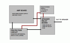
I have an idea for clipping and short circuit protection for this amp. I have studied Rod Elliot's SIM circuit and have adapted it to switch a normally closed relay that will interrupt power to the output relays.
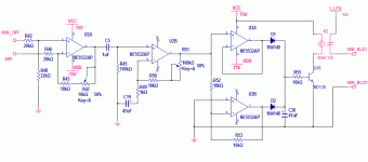
Simulation of the circuit shows extreme sensitivity to clipping and short circuit. It monitors the differential pair for differences, and has no impact on the distortion level of the amp.
Is this going too far? His original circuit drives an LED to give a visual indication of clipping. This version would cut the output to the speakers.
Here's a sketch of what I have in mind:
Attachments
relays manage to cut AC currents rather well. This is due to the zero current extinguishing the arc across the open contacts at some point in the waveform.
If there is DC to be cut, the arc does not extinguish and the relay contacts just melt into a molten mess of conductive plasma until something else gives up.
If there is DC to be cut, the arc does not extinguish and the relay contacts just melt into a molten mess of conductive plasma until something else gives up.
Here is the (slightly) modified circuit. I could use the NE5532's or a single quad. Rod advises that better performance results with a higher quality op-amp.
There is adjustment for sensitivity and will need to be calibrated. C20 could be changed to increase the amount of time the relay stays open.
There is adjustment for sensitivity and will need to be calibrated. C20 could be changed to increase the amount of time the relay stays open.
Attachments
AndrewT said:
If there is DC to be cut, the arc does not extinguish and the relay contacts just melt into a molten mess of conductive plasma until something else gives up.
Hi Andrew,
Arcing would not be a problem on a relay rated for high DC voltage such as:
http://oeiwcsnts1.omron.com/ocb_pdf...91192F786256FC7005BF53A/$File/D20G2RG0305.pdf
I would also have an appropriately sized fuse on the output and, of course, fuses on the rails.
Hi,
try it, but I see 8A @ 250Vac on the case and datasheet shows 8A @ 125Vdc in the spec.
These only apply to resistive loadings.
I think your rail fuse/s will blow first if they are correctly rated.
Will the output devices survive that length of time.
Don't take the risk with your target performance with a speaker fuse.
AndrewT said:Hi,
try it, but I see 8A @ 250Vac on the case and datasheet shows 8A @ 125Vdc in the spec.
I think your rail fuse/s will blow first if they are correctly rated.
Will the output devices survive that length of time.
Don't take the risk with your target performance with a speaker fuse.
This protection circuit for catastrophic failure prevention, not something that's going to trigger on a regular basis. The amp will deliver 170 watts into 8 ohms before clipping. This is well above the input sensitivity of the amp, so there is some leeway there.
It may be completely redundant, that the fuses will do their job and blow, but it's not a big deal to build and it can do what the fuses won't do - prevent clipping.
The output devices are pretty robust. Still, the protection has to react fast enough. Any ideas on making it detect an existing short before power up of the amp board?
If the protection circuit works as expected, I won't use a fuse on the output.
AndrewT said:relay cannot prevent clipping. It's far too slow probably one hundred times too slow.
Circuit detects clipping, opens relay. The relay stays open until clipping ceases and C20 discharges.
- Status
- Not open for further replies.
- Home
- Amplifiers
- Solid State
- Help with this amp? A patchwork product of simulation


