Hello all.
I am starting to design an offline SMPS, based on half-bridge topology, using a ETD39 core with 1 primary and 2 main secondaries + 1 aux. secondary, intended to give about +/-55V at 500W and 15V for the housekeeping.
I will try voltage-mode regulation with a simple SG3525.
I have seen some designs, mainly in PC power supplies, that implement overcurrent protection (and some kind of cycle-by-cycle current control as the SG3525 permits), but they always use a small current sense transformer as the sensing element.
Is it possible to use a small valued power resistor?
For example, a 0.1ohm/5W resistor should be enough to activate a transistor with a 6A current flowing through it, with a loss of only 3.6W in the worst case.
Is this loss the unique cause for the general tendence to avoid the resistor or is there any other cause for using a more expensive transformer?
Thanks!
No, You can not use resistor at this topology, because both sides of primary are floating... You need a current transformer, but it's not a big deal - just 50 turns of wire on 10-15mm ferrite toroid core for secondary. and for primary 1 turn - just pass "cold" side of primary via the core. You can find a lot of such tr-rs in old SMPS. The secondary should be connected to bridge (4x1N4148) and 20 Ohm load - it will provide (Iout/50 )*20= 400mV/A. Additional R-C filter is desired to remove overshoots.
Attachments
However, I still don't understand what's the problem with a sense resistor. I assume that it will only "read" current half cycle, when the lower mosfet is on.
My proposal is to put the resistor from the low side mosfet source to gnd.
Shouldn't this be enough for rough overload protection? It worked very well for me in a Class-D power amplifier.
Pierre
My proposal is to put the resistor from the low side mosfet source to gnd.
Shouldn't this be enough for rough overload protection? It worked very well for me in a Class-D power amplifier.
Pierre
The problem with resistor current sensing arises from its lack of mains isolation except when the control circuit is already on the mains side
Current-transformer sensing solves the issolation issue
Also remember that asymetric pulse-by-pulse current limiting drives the transformer into saturation and destroys the switches. Inmediate shutdown is required to avoid that
Current-transformer sensing solves the issolation issue
Also remember that asymetric pulse-by-pulse current limiting drives the transformer into saturation and destroys the switches. Inmediate shutdown is required to avoid that
Thanks, Eva.
In my case the control circuitry is already on the mains side, but thinking about it twice, asymmetric current control can be dangerous as you said, unless I only use voltage-mode control and use the current sensing signal externally to activate the shutdown pin of the controller with a latch.
Using voltage-mode only can be ok?
My proposal is to put the resistor from the low side mosfet source to gnd.
Shouldn't this be enough for rough overload protection? It worked very well for me in a Class-D power amplifier.
You can use it for average-power overload protection, in such case it's better to place Your sensor in the negative rail of the H-bridge, but in Your 1st post You asked about cycle-by-cycle current control - in this case You have use current tr-r, because You can't control 3525 with low-side pulses only.
If average-power protection is enough for You (it's slow and not so reliable) - to my opinion You can't use 3525 built-in protection as-is (in overcurrent mode output pulses can get very asymmetric) - You will need to design some trigger-like protection mechanism with LM393 etc.,
if it DIY project and not mass-production - take 20 minutes and wind 50 turns 🙂...
I think DEM has answered my question.
Only a thought more: why do you say average-power detection is slow? I think that it will detect any overcurrent (although only in the negative leg of the h-bridge, ok) and can trigger shutdown with a fast latch very quickly.
Only a thought more: why do you say average-power detection is slow? I think that it will detect any overcurrent (although only in the negative leg of the h-bridge, ok) and can trigger shutdown with a fast latch very quickly.
Sensing Resistor
adding to Eva's comments, it also gives only "half" the picture, as you will only be sensing the current through the lower MOSFET, and not through both. You need to sense the current through both MOSFETs or you will end up with an imbalance, leading to "walking' of the core toward saturation, and destroying one or both MOSFETs in the process.
BTW, even though you are using the SG3525 voltage-mode chip, you can implement a crude cycle-by-cycle current limiting by taking the output from the current-sensing transformer to a signal-conditioning op-amp and then on to pin 10 (SHUTDOWN) of the 3525. Whenever the output from the op-amp exceeds pin 10's threshhold (which, I believe, is 1.0V), if the duration is short enough, the SS capacitor will not discharge enough to trigger a new softstart cycle, enabling you to realize cycle-by-cycle current limiting this way.
Please keep us posted of your progress ans post pics if/when available.
Steve
why do you say average-power detection is slow?
I didn't say that it's slow, I mean that YOU must make it slow to be average - for example Your amplifier "normal" consumption is 100W, You want to shutdown Your supply if awerage power will more than 150W during 2 seconds (someone connected 4Ohm load instead of 8) - than You shutdown Your supply for 10 seconds. Average protection will not protect against short-circuit...
But if You make it fast (comparable with pulse width) - You will go to asymmetries and will get a lot of "goods" that N-Channel described above...
what about this?
Hello!
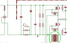
What do you think about this current sensing?
The green circle is arout 10 piece of SMD resistor. Each one is 1ohm/1206 size.
This is a part is a 500-700W half bridge SMPS. currently, there's no PFC before it, but i'm planning making one...
Hello!
What do you think about this current sensing?
The green circle is arout 10 piece of SMD resistor. Each one is 1ohm/1206 size.
This is a part is a 500-700W half bridge SMPS. currently, there's no PFC before it, but i'm planning making one...
Attachments
Sorry, Danko, but your figure doesn't show correct.
Could you post it again?
Best regards,
Pierre
Could you post it again?
Best regards,
Pierre
Pierre said:Sorry, Danko, but your figure doesn't show correct.
Could you post it again?
Best regards,
Pierre
I uploaded the picture to my server: http://sziget.mine.nu/~danko/aramkor/testbed/9/current_sensing.jpg
Maybe, this time this is OK 🙂
--
Danko
The picture is cut below the current sense resistors. I thought you were trying to show us how the current limiting is done, not only the sense resistors. Your arrangement is just how I was proposing: source of the low side mosfet to GND. But, what are you doing with that signal?
Pierre
Pierre
Oh, sorry. I thought there was some kind of technical problem with the picture.
Here's the current limiting part of my schematic, but ths is now only a schematic, ha couldn't test the circuit, becouse of my exams. I'm an Electrical Engineer student... 🙂
I know, there should be one or more capacitors near R8 R33. This/theese capacitor(s) will be determined by experiments.
here's the schematic: http://sziget.mine.nu/~danko/aramkor/testbed/9/current_sensing2.jpg
I turned off the part's values, becouse with the values, the picture would be very caotic...
(I have removed the previous pic from my server, becouse that's also uploaded to the forum)
I am glad you are also using a IR2110/3. My design is also based on it. If everything works ok, perhaps I will move to a gate driver transformer, although that's more expensive.
Have you done any test on the supply so far? Does it work well (apart from the current limiting)?
About the current limit, what is the control chip number? If we don't know that, we will not be able to help you.
Best regards,
Pierre
Have you done any test on the supply so far? Does it work well (apart from the current limiting)?
About the current limit, what is the control chip number? If we don't know that, we will not be able to help you.
Best regards,
Pierre
Pierre said:I am glad you are also using a IR2110/3. My design is also based on it. If everything works ok, perhaps I will move to a gate driver transformer, although that's more expensive.
Have you done any test on the supply so far? Does it work well (apart from the current limiting)?
About the current limit, what is the control chip number? If we don't know that, we will not be able to help you.
Best regards,
Pierre
I dealt a lot with the voltage-stabilizing. The feedback always oscillated. Finally, I hope i made it OK. Now the feedback (voltage) is made with a TL431, and an optocoupler. the previous version worked with "wired-in" Z-diode, and optocoupler.
About the gate-driver-transformer. I dont like it, becouse it is hard (or just harder) to find, than an IC.
But, to tell the truth, it is almost inpossible to destroy a gate driver transformer. I have killet about 10 IR2113 ... 🙁
In this version of my SMPS I use TL494, as PWM-controller, but i'm planning to use Onsemi's MC<I-dont-know-the-exact-number> Resonant Mode PWM Controller, to reduce switching loss, and to reduce EMI.
I wish you best of luck with your design.
What do you mean with "Wired Z-diode"?
Did you succeed in putting it to work without feedback (always at maximum duty cycle) first? What power level did you reach?
Best regards,
Pierre
What do you mean with "Wired Z-diode"?
Did you succeed in putting it to work without feedback (always at maximum duty cycle) first? What power level did you reach?
Best regards,
Pierre
Pierre said:I wish you best of luck with your design.
What do you mean with "Wired Z-diode"?
Did you succeed in putting it to work without feedback (always at maximum duty cycle) first? What power level did you reach?
Best regards,
Pierre
Thanks for the wishes 🙂
I mean under "wired z-diode", that i soldered the diode, and a few resistors to the PCB with wires. At that stage, I was testing a few stabilizating methods.
Without feedback, it worked good, but /as I counted on it/ the output voltage dropped a lot, when I put a big dummyload on the SMPS.
As far as I remember, the highest output power, I measured is about 600-650watts. The efficiency (this was the goal of that measurement) was about 90-93%.
I thought, that was a little bit too much for the switching devices (IRF740), so I haven't loaded the SMPS such bit load, since that time. I have a few APT5015BVR MOSFETS (500V/32A :-D ), with them, the SMPS can deliver more power. But there's a limitation of the half bridge topology. I think, using half-bridge for more than 900-1000watts is not economic enough. For such output power, the full bridge is better. I think.
Bye: Danko
OnSemi Controller
Danko-
I think you are referring to several chips from OnSemi.
1) The PWM chip is the MC33025. This is essentially the next-
generation SG3525 with the follwing goodies added: Wide-
bandwidth error amp, high-current totem-pole outputs (+/-2A),
Higher-frequency oscillator (2MHz), and either voltage- or
current-mode operation. Pin-out is similar to the '3525, but
there are a few differences. (See the datasheets at OnSemi's
website.)
2) the Resonant-mode chips are:
a) MC33066 Resonant-mode controller
b) MC33067 Zero-switching Resonant-mode controller.
The difference between the '33066 and the '33067 is that the '33067 achieves either true zero-voltage, or zero-current switching depending on what method of control you'like to have.
I have used the MC33025 in both DC-DC and Off-line converters, both hi- and low-power, and report good results with it. AND, it works well with the MPIC2113 (OnSemi's obsoleted version of the IR2113). I have not, as yet, tackled the variable-frequency control methods like resonant and quasi-resonant. Too much math there. UGH! Anywho, If you can get the extended-temp range PWM chip (33025) you will find you get pretty good results with it.
BTW, 90-93% efficiency for a 600-700W converter is VERY good. you must be very good in your overall design to achieve that figure the first time!
Post more pics.
Steve
Danko-
I think you are referring to several chips from OnSemi.
1) The PWM chip is the MC33025. This is essentially the next-
generation SG3525 with the follwing goodies added: Wide-
bandwidth error amp, high-current totem-pole outputs (+/-2A),
Higher-frequency oscillator (2MHz), and either voltage- or
current-mode operation. Pin-out is similar to the '3525, but
there are a few differences. (See the datasheets at OnSemi's
website.)
2) the Resonant-mode chips are:
a) MC33066 Resonant-mode controller
b) MC33067 Zero-switching Resonant-mode controller.
The difference between the '33066 and the '33067 is that the '33067 achieves either true zero-voltage, or zero-current switching depending on what method of control you'like to have.
I have used the MC33025 in both DC-DC and Off-line converters, both hi- and low-power, and report good results with it. AND, it works well with the MPIC2113 (OnSemi's obsoleted version of the IR2113). I have not, as yet, tackled the variable-frequency control methods like resonant and quasi-resonant. Too much math there. UGH!
Anywho, If you can get the extended-temp range PWM chip (33025) you will find you get pretty good results with it.BTW, 90-93% efficiency for a 600-700W converter is VERY good. you must be very good in your overall design to achieve that figure the first time!
Post more pics.
Steve
- Status
- Not open for further replies.
- Home
- Amplifiers
- Power Supplies
- Help with SMPS current sensing