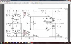
Hi guys I have a little problem: could one of you please have a look at the schematic hopefully visible here) and tell me if the elcaps circled in red should be the same or different?
I have a slight problem in that I recapped the amp and replaced like for like, with better grade caps (Panasonic NHG 105 degree instead of the original 85 degree Phillips). Both sides were 4.7uF 100V.
The new cap on the positive side (one in each channel, both channels) start bulging and lose capacitance immedicately.
The amp works fine and I can adjust the bias pot to 60mV (measured between positive and negative emitter) as suggested, but when measuring the trim pot there is 400ohms on one side and 600ohms on the other (bulging) side.
So my other question: Is the trimpot there to adjust the balance between the positive and negative side of the channel or does it adjust the bias current for both sides equally?
Basically, someone please explain this schematic to me...
Many thanks
Attachments
Last edited:
Pretty sure I did as it is indicated on the board, (although I have been known to be dozy on occasion. So I will check again.
Do you have any explanation other than reverse polarity? The resistors in-line with the trim-pot are different on each side.
But surely the caps are just decoupling caps to ground?
Do you have any explanation other than reverse polarity? The resistors in-line with the trim-pot are different on each side.
But surely the caps are just decoupling caps to ground?
Did you check the polarity, with a meter or by tracing out the circuit? I would not necessarily trust the markings on the circuit board. I can't think what else would cause good electrolytics to blow up like that.
The trim pot sets the output bias current, and the voltage across all 4 of the 0.33R should be the same.
Caps are the right polarity. Are you mistaking the positive cap for the negative cap, and vice versa,
in their locations on the pcb?
Caps are the right polarity. Are you mistaking the positive cap for the negative cap, and vice versa,
in their locations on the pcb?
Last edited:
ubergeek, I think you have solved my problem, I just looked at the position of the elcaps on the negative channels and they are both the opposite way, so naughty manufacturer/pcb etcher!
Rama, many thanks: which caps are right, both at 4.7uF or as shown in the schematic? Me thinks they should be the same?
Rama, many thanks: which caps are right, both at 4.7uF or as shown in the schematic? Me thinks they should be the same?
which caps are right, both at 4.7uF or as shown in the schematic? Me thinks they should be the same?
Yes.
The value isn't critical, its decoupling for the cascode transistors. If 10uF fits in both positions upgrade the 4u7 to a 10u for better decoupling that side.
Its an odd arrangement, the rail decoupling and cascode decoupling are linked. A better scheme would decouple the rails straight to ground, and decouple the cascode bases to the rails (not to ground), since the point of a cascode is to take voltage swing away from the amplifying transitor's collector, and in these VAS circuits the rail is the reference point for the incoming signal, not ground.
Its an odd arrangement, the rail decoupling and cascode decoupling are linked. A better scheme would decouple the rails straight to ground, and decouple the cascode bases to the rails (not to ground), since the point of a cascode is to take voltage swing away from the amplifying transitor's collector, and in these VAS circuits the rail is the reference point for the incoming signal, not ground.
Why do you think the two resistors have to be the same? After all, the BC550C has an emitter only on one side too.The resistors in-line with the trim-pot are different on each side.
But surely the caps are just decoupling caps to ground?
As for those caps, useless, leave them out.
Mona
The new cap on the positive side (one in each channel, both channels) start bulging and lose capacitance immedicately.
Two possibilities ... backwards or overvoltage.
Take a close look at the schematic ... notice they are shown in opposite directions... on the + rail the cap + ties to the transistor... on the negative rail it's the other way around - to the transistor. In that moment it's real easy to get one of them backward, even if it looks right to you. Also note they are specified as two different values .. 4.7u on the + rail and 10u on the negative.
Hi guys, thank you all very much, I think we have solved the immediate problem. very informative, too.
As mark has already started to talk about this how do you think this amp could be improved?
As mark has already started to talk about this how do you think this amp could be improved?
Well, it is on the bench in bits, so we could all have a look if it is possible to improve things, couldn't we?
I'm not sure if leaving them out is a good idea -- they may be important to stability .. or help reduce turn-on/off pop.
There are good, practicing engineers who sometimes forget that a ratio between electrolytic capacitors isn't quite the same as a ratio between 1% resistors -- or even 10% resistors -- the typical -20/+80% scrambles that. But maybe these originals are a more tightly specified flavor?😉
On the bench in bits? How 'bout some pics?
Cheers,
Rick
I tend to agree about losing the 4u7 and 10uF caps - they are only fighting the caps to the rails and maybe reducing the amp performance. The cascode bases should be decoupled to the rails only.
And yes the bias circuit is not symmetrical. However it has a big flaw - if the trimmer fails open circuit the entire amp self-destructs. The base of the Vbe spreader transistor should connect to the wiper and also the upper end of the trimmer. Then any failure of the trimmer will turn the BC550C on hard and _reduce_ the bias voltage, not increase it. Currently if the wiper goes open circuit the transistor turns off, the bias increases and the output devices cook.
And yes the bias circuit is not symmetrical. However it has a big flaw - if the trimmer fails open circuit the entire amp self-destructs. The base of the Vbe spreader transistor should connect to the wiper and also the upper end of the trimmer. Then any failure of the trimmer will turn the BC550C on hard and _reduce_ the bias voltage, not increase it. Currently if the wiper goes open circuit the transistor turns off, the bias increases and the output devices cook.
Last edited:
It continues to surprise me, just how many amps out there DO ignore that simple precaution -- every trimmer/pot gets dirty or fails outright, someday.
Thanks everybody. Mark, I bet you're a good chess player, what with always being a step ahead...
I will have a look at how to best implement your suggestion.
I will have a look at how to best implement your suggestion.
Ah yes, the old '70s Elektor amp bias circuit. Smart designers were implementing failsafe bias configurations even then, but it took a while to trickle through.
Amazingly enough, non-failsafe bias configurations have not gone entirely extinct. Onkyo surround receivers may still be using them to this day (at least they still did in ~2012)...
Amazingly enough, non-failsafe bias configurations have not gone entirely extinct. Onkyo surround receivers may still be using them to this day (at least they still did in ~2012)...
- Home
- Amplifiers
- Solid State
- Help with schematic