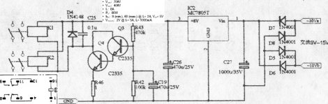
I've assembled a PCB for a "Marantz-like" 7c preamp. I can't get the thing to work. My feeling is that the power supply replacement transistors I've used are not the right ones... I am trying to troubleshoot it but my limited knowledge of electronics is not allowing me to fully understand the nature of the problem... Taking it a step at a time, I am now trying to fix a problem with the couple of relays that mute the output. They don't change state ever so the signal is shorted to ground always. I've attached a picture of the relay circuit showing the relays I am using. The relays are OMRON DPDT rated for 5vdc. It also shows the transistors I am using. Can anyone tell me what I am doing wrong? Please?
Attachments
if your relay is out of circuit can you get it to contact????
apply the 5volts and put a mter over to see if you are closing or not. If there is no change you may have a faulty relay. Or you may have a faulty power supply that can be checked in much the same way. One more thought are they NO or NC relays.
Mark
apply the 5volts and put a mter over to see if you are closing or not. If there is no change you may have a faulty relay. Or you may have a faulty power supply that can be checked in much the same way. One more thought are they NO or NC relays.
Mark
If you got the 5 Volt from the regulater, then make sure that the pin configurations of the replacement transistors are the same as the on the original... If not, transistors will not work (pull the relays) or even burn off...
Keep us informed

Keep us informed
Circuit as shown will not work with silicon transistors. (Is it old enough to be Germanum?)
C19 charges slowly, which keeps Q3 Q4 Off until the C19 voltage rises enough to turn-on Q3 Q4.
C19 rises toward 5V*(100K/100K+470K), or 0.88 Volts. Silicon transistors need 0.6V to turn-on; in this Darlington affair you need 1.1V to 1.3V at the Base of Q3 to turn-on Q3 Q4 and turn-on the relay.
Either the schematic is wrong or they used odd transistors.
Quick-Fix: change R43 470K to 220K. Now C19 will charge toward 1.56 Volts, enough to make any silicon Darlington pass enough current for a reed-relay. After turn-on, the maximum possible Base current is 5V/220K= 0.022mA (and probably much less), which will not harm any transistor.
> a "Marantz-like" 7c preamp. I can't get the thing to work.
If you meant the total preamp: you do not need mute relays to have a preamp, they are just a frill to save your speakers from the preamp thumping some kilo-watt amplifier. Skip this circuit for now, just tack jumper wires across the relay contacts to pass the signal. Jump 11 to 9, 6 to 8. Then get on with checking the rest of your work. When working with a possibly unhappy preamp, keep the power amp input level controls down to 1/4 until you hear it pass a nice soft signal.
mwmkravchenko: I don't know if they are NO or NC. The pin configuration fits the PCB and it's rated for 5vdc so I didn't check anything else... I think they work. I replaced them with new ones a couple of times and had the some problem...
JOE DIRT: If they are not relays what are they???
ACD: The 5 volts are there and the pin configuration for the transistors is the same
Thank you all
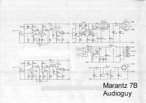
Here's the schematic that this is part of. The relay's (or whatever they are) connect to the outputs.
JOE DIRT: If they are not relays what are they???
ACD: The 5 volts are there and the pin configuration for the transistors is the same
Thank you all
Here's the schematic that this is part of. The relay's (or whatever they are) connect to the outputs.
Attachments
ppereira said:
JOE DIRT: If they are not relays what are they???
I'm sure he meant they are NO relays, as in "normally open".
Do you have a part number on those relays? Some relays are polarized.
Try to measure voltage across D4 when powering up the amp. You should see 5 volts if so the relays are either of the wrong type or malfunctioning. If not the transistors is not doing it’s job. Part number of transistor?
I did mean NO (normally open) relays
replace D4 and C25....a signal diode is the worst thing to use as a clamp for a relay it is used to prevent back EMF....replace it with a 1N4002....the capacitor should remain as a ceramic type what this does is avoids chatter of the relay....a 50 volt NPO will work fine
DIRT®
replace D4 and C25....a signal diode is the worst thing to use as a clamp for a relay it is used to prevent back EMF....replace it with a 1N4002....the capacitor should remain as a ceramic type what this does is avoids chatter of the relay....a 50 volt NPO will work fine
DIRT®
Sorry Joe 🙂
Part numbers:
relay - G6A-234P-ST-US (OMRON)
http://www.mouser.com/index.cfm?handler=displayproduct&lstdispproductid=210072
transistors: 333-MJE13007 (MOUSER)
http://www.mouser.com/index.cfm?handler=displayproduct&lstdispproductid=364211
As far as the cap I didn't have any .1uf that fit the PCB available so I used a .01uf instead... Is that OK?
Thanks again...
Abre-te relays!!!!
De nada!!
If you remove the relays you will loose the mutting function..and you must turn on the preamp before the power amp....have you checked the relays disconected from the circuit ans connected to 5 volt suplly...and see if they opened???
Um abraço
ppereira said:Yes. 4.98V. I just checked. Can I just remove the relay altogether?
Obrigado
De nada!!
If you remove the relays you will loose the mutting function..and you must turn on the preamp before the power amp....have you checked the relays disconected from the circuit ans connected to 5 volt suplly...and see if they opened???
Um abraço
This is probably a waste of time... But I'm to stubborn to give up... I've been working on this thing for days now... Even when I removed the relays and got it to work there was way too much hum and noise....
I think I am going to build something else... from scratch this time...
By the way if anyone is interested you can buy these PCB's on ebay...
http://cgi6.ebay.com/ws/eBayISAPI.d...=18audioguy&include=0&since=-1&sort=3&rows=25
Hey Tube_Dude what part of Portugal are you from?
I think I am going to build something else... from scratch this time...
By the way if anyone is interested you can buy these PCB's on ebay...
http://cgi6.ebay.com/ws/eBayISAPI.d...=18audioguy&include=0&since=-1&sort=3&rows=25
Hey Tube_Dude what part of Portugal are you from?
ppereira said:
Hey Tube_Dude what part of Portugal are you from?
Aveiro!!...
Á nossa!!!

ppereira said:This is probably a waste of time... But I'm to stubborn to give up... I've been working on this thing for days now... Even when I removed the relays and got it to work there was way too much hum and noise....
Don’t give up just jet, the relay’s appears to be polarized, e.g. pin 1 has to be connected high and pin 16 low. Check that this conforms to your pcb.
- Status
- Not open for further replies.
- Home
- Amplifiers
- Solid State
- Help with relay