don't know yet. just finished the electronic crossover for the woofs and now in the middle of building the amp for the mids and highs.
They look great. I like that you went with OB bass, rather than following Qualio's scheme.
But please tell me you didn't buy those crossover components based solely on chatGPT's answers. 😱
I asked CHATGPT A.I. the values of the components in the Qualio I.Q. crossover.
But please tell me you didn't buy those crossover components based solely on chatGPT's answers. 😱
Went based on Qualio's disclosed information (slopes and hi/lo pass freq. and cut off's) on what they is their crossover. A.I. was just used to verify what I got from actual calculations.
Hi, I really like the look of what you've done, but I'm confused about a couple of things - hope you don't mind me asking.
First, I saw a post you put on the DIY Biamp 6-24 thread a few days ago. It implies you're intending to use an LX mini active crossover between the bass and midrange drivers, and then you're adding a Biamp 6-24 active crossover to the midrange feed, to divide the mid and tweeter. Is that correct?
If so, what is the passive crossover for?
Second, assuming that there is a purpose to the passive crossover, are you saying you designed it using standard calculators, without any measurements or modelling, and haven't prototyped the speakers with cheaper components?
Going to listen for a while with the passive. Then Ill listen a while with the active setup. I like having options. Sometimes you feel like a nut, sometimes you don't. I'll eventuality end up with what sounds best to me. If I don't try out different directions, I'll never know.
OK. I'm crossing all my fingers and toes for you now, because that's quite a gamble, splashing out on Milflex and Duelund caps for a crossover that hasn't been designed based on measurements of the drivers in the baffle, and without any modelling in advance.
I expect you'll need to make some measurements in order to optimise both active and passive options. It's not easy to do it by ear. Those are nice drivers, and you've done an impressive construction job - it would be a shame not to get the best out of them.
I expect you'll need to make some measurements in order to optimise both active and passive options. It's not easy to do it by ear. Those are nice drivers, and you've done an impressive construction job - it would be a shame not to get the best out of them.
here's a very interesting web page on making a Qualio IQ clone:
http://tweakaudio.com/EVS-2/Speaker_building_info.html
http://tweakaudio.com/EVS-2/Speaker_building_info.html
Hmm. I got to the second sentence, where he says "speakers are actually quite simple", and realised the guy is (to be blunt) an idiot.
There's pretty much nothing in the document about actual speaker design - it's just tweaking, some of which is more likely to ruin a design than improve it. If you want to understand open baffle speakers, avoid tweakaudio and spend time on LinkwitzLab instead.
There's pretty much nothing in the document about actual speaker design - it's just tweaking, some of which is more likely to ruin a design than improve it. If you want to understand open baffle speakers, avoid tweakaudio and spend time on LinkwitzLab instead.
Ok, that last post was a bit harsh - my apologies. But I see a lot of people posting on here, just getting interested in building speakers, starting out, and nothing causes more grief for them than the idea that it's simple. Because it really isn't.
(Just look at the OP on this thread - he clearly got discouraged, which is a huge shame. But if someone thinks it's going to be easy, spends a chunk of money, then doesn't get good results, they might well throw the towel in rather than dig deeper. It's the idea that it's simple that does the damage.)
(Just look at the OP on this thread - he clearly got discouraged, which is a huge shame. But if someone thinks it's going to be easy, spends a chunk of money, then doesn't get good results, they might well throw the towel in rather than dig deeper. It's the idea that it's simple that does the damage.)
Last edited:
I asked him if he was going to complete this project:here's a very interesting web page on making a Qualio IQ clone:
http://tweakaudio.com/EVS-2/Speaker_building_info.html
My focus is on my open baffle speaker that I am tweaking right now. Qualio just updated their speaker with better parts and bi-amping capability......doing some of the things I suggested before. Of course, there is lots more one can do. Give me a [filtered] if you want to discuss. Audiogon emails are not for serious talks.
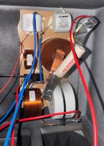
Other 'real life' photo of the filter;Hi as my first loudspeaker I am building a "clone" of the qualio-iq speaker.
There are much information about the speaker on their website and from test.
I can't find out where the resistor and one of the capacitors goes. It looks like they site on the midrange
Some pictures of the new and updated filter taken from the website
View attachment 1341480
View attachment 1341481
View attachment 1341475
https://www.whatsbestforum.com/threads/qualio-audio-join-the-wbf-forums.37058/#post-908026
Dear all,
sorry for my very long absence. I was too busy.
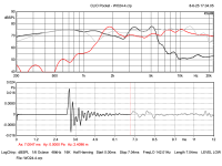
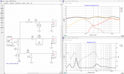
Finally, I took the time to measure the drivers of my prototype.
So I set up my clio-pocket (btw. amazing tool) in my garage and did measure frequency responses from 1m distance with quasi anechoic cut off at around 200Hz.
Below this, we're in goods ands anyway. Nevertheless I merged near- and far-field measurements as well and they turned out great with a 3dB peak at 40Hz.
I simulated the volume and port size via ajhorn (ca 73L port dia 4,7cm 10cm long). I did not care too much as I rebuild the woofer chamber according to the same dimension and trusted the guys from Qualio.
Drivers:
Mundorf AMT17D2.2
SB Satori WO24P-4 (4 Ohm)
SB Satori MR16P-8 (8 Ohm!!)
First I was slightly shocked when I saw the measurements. Especially the huge dip of the MR16P-8 at around 1200Hz. (grey curve)
But after having designed the crossover, all major dips seem to be gone because of some nice phase effects. Thanks @jdavison for figuring out the parts, which was a very good start for me. However I made a few changes.
Kudos to the guys at Qualio. They are amazing and know what they are doing. I cannot express this enough!
Please find the details in the images and let me know if you need some data files or information.
Mind the polarity of the drivers!
R1 is important to level out the mid woofer. Use for R2 3 Ohms to ca. 20 Ohms (4 Ohms my choice) to throttle down the highs to your liking. Place R2 like in the drawing before the filter!
For our tube freaks: The first filter left hand side (R3, C4, L4) is an optional impedance correction which completely removes the impedance hump at around 1200Hz. 🙂
I will order the parts and be back (hopefully) soon with real life measurements.
Best
PS. The SPL curves do not reflect the actual efficiency of the speaker. A final efficiency chart will come with the final build
sorry for my very long absence. I was too busy.
Finally, I took the time to measure the drivers of my prototype.
So I set up my clio-pocket (btw. amazing tool) in my garage and did measure frequency responses from 1m distance with quasi anechoic cut off at around 200Hz.
Below this, we're in goods ands anyway. Nevertheless I merged near- and far-field measurements as well and they turned out great with a 3dB peak at 40Hz.
I simulated the volume and port size via ajhorn (ca 73L port dia 4,7cm 10cm long). I did not care too much as I rebuild the woofer chamber according to the same dimension and trusted the guys from Qualio.
Drivers:
Mundorf AMT17D2.2
SB Satori WO24P-4 (4 Ohm)
SB Satori MR16P-8 (8 Ohm!!)
First I was slightly shocked when I saw the measurements. Especially the huge dip of the MR16P-8 at around 1200Hz. (grey curve)
But after having designed the crossover, all major dips seem to be gone because of some nice phase effects. Thanks @jdavison for figuring out the parts, which was a very good start for me. However I made a few changes.
Kudos to the guys at Qualio. They are amazing and know what they are doing. I cannot express this enough!
Please find the details in the images and let me know if you need some data files or information.
Mind the polarity of the drivers!
R1 is important to level out the mid woofer. Use for R2 3 Ohms to ca. 20 Ohms (4 Ohms my choice) to throttle down the highs to your liking. Place R2 like in the drawing before the filter!
For our tube freaks: The first filter left hand side (R3, C4, L4) is an optional impedance correction which completely removes the impedance hump at around 1200Hz. 🙂
I will order the parts and be back (hopefully) soon with real life measurements.
Best
PS. The SPL curves do not reflect the actual efficiency of the speaker. A final efficiency chart will come with the final build
Attachments
Last edited:

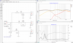
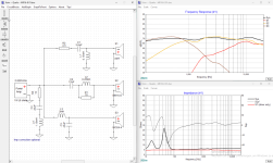
Dear all, please do not use my values above. I messed up the phase data / time alignment :-(
New calculations look good though.
I'll get back to you once I double checked this time.
Sorry for the inconvenience. Won't take long
Cheers
New calculations look good though.
I'll get back to you once I double checked this time.
Sorry for the inconvenience. Won't take long
Cheers
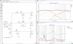
Here is the final crossover calculation for my prototype.
Please do not use my designs above.
What happened:
Usually, I use a UMIK-1 and REW for SPL measurements, with the Clio Pocket only for T/S parameter measurements. REW can time-align all the measurement curves, and the exported files work fine in XSim and VituixCAD.
This time, I wanted to use the Clio Pocket for SPL as well, because I believe its mic and calibration are superior.
What I didn’t realize: Clio does not export time-alignment to the text file, even if you set the marker to the first IR peak. As a result, the phase and driver alignment in simulation tools are incorrect.
The solution: Fortunately, VituixCAD has an “IR to FR Converter” tool that can read Clio’s .crp files. There, you can set the reference time (at the IR peak) and cut off the first reflection (for example, at 1 m mic-to-cone distance, the first reflection arrives at about 7 ms). This makes the frequency data reliable above ~250 Hz. I’ll add a nearfield measurement for the low frequencies once I have the soldered crossover in place.
My findings:
I suspect that the crossover parts shown in Qualio’s photos are just dummies—their part values do not make any sense to me given their own crossover descriptions.
There’s still a large dip around 1,500 Hz in my prototype’s response, which is very typical for wideband driver implementations—especially in open baffle or minimal crossover concepts.
It's a trade-off: you can get coherent point-source sound and no crossover phase issues, but at the cost of a less flat frequency response.
Real live measurements will come…
Attachments
Hi everybody, I recently bought a Qualio IQ, and I thought about upgrading it to Ultra level and also incorporating that resistor at the outside to the Xover board to avoid the long cable runs.
Based on my fotos, the Xover values are as follows (inserted into picture from first post). Would that make sense? Added a foto of the actual Xover.
Based on my fotos, the Xover values are as follows (inserted into picture from first post). Would that make sense? Added a foto of the actual Xover.
Attachments

- Home
- Loudspeakers
- Multi-Way
- help with Qualio-IQ filter