I purchased this amp a few days ago to compare it to my old ATI 1807 amp which I'm currently using and quite liking but wanted to upgrade to something better.
However, I wanted to check what it outputs because I will connect it directly to my drivers (using DSP for a crossover).
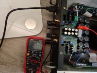
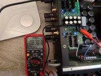
!!! I've measured ~0,4v (405mV) constant DC voltage on the Left channel and about 0,08-0,12v (120mV) DC on the right channel !!! Clearly cannot connect it to a tweeter!
Is the unit defective? It has a break-in runtime of around 3 days before the test and was warming up for 4 hours but the voltage is similar when cold.
My old ATI amp is outputting between 0,0015v (1,5mV) to 0,0045v (4,5mV) between all 7 channels which I think is acceptable!
P.S. I've checked the test points on the Input stage and saw a difference of around 12-15mV between L and R channels.
P.S.2 If I like the amp I'm ready to explore the way of using three amps for my 3-way speakers but if it outputs so much DC I won't be able to do this...
However, I wanted to check what it outputs because I will connect it directly to my drivers (using DSP for a crossover).
!!! I've measured ~0,4v (405mV) constant DC voltage on the Left channel and about 0,08-0,12v (120mV) DC on the right channel !!! Clearly cannot connect it to a tweeter!
Is the unit defective? It has a break-in runtime of around 3 days before the test and was warming up for 4 hours but the voltage is similar when cold.
My old ATI amp is outputting between 0,0015v (1,5mV) to 0,0045v (4,5mV) between all 7 channels which I think is acceptable!
P.S. I've checked the test points on the Input stage and saw a difference of around 12-15mV between L and R channels.
P.S.2 If I like the amp I'm ready to explore the way of using three amps for my 3-way speakers but if it outputs so much DC I won't be able to do this...
Attachments
Last edited:
This is not a major problem. If the amp is new, check with the mfr first for the best advice.
If the amp is used, the DC offset likely needs a slight internal adjustment, one per channel.
Connection to a passive system mid or tweeter is fine, since there are high pass filter DC blocking capacitors.
An active system will pass the DC on to the drivers, though.
It will cause no harm to a woofer, just a slight cone displacement from center.
Check with the mfr for the proper adjustment procedure. You may want to have a local technician
make the adjustments for you, preferably in your home to account for the AC line voltage.
Last edited:
short the RCA jacks and check it again. Maybe hook up your preamp.
Also, when you hook up a pair of speakers, the DC offset may come down. So maybe try a cheap set of speakers.
Also, when you hook up a pair of speakers, the DC offset may come down. So maybe try a cheap set of speakers.
I have done the same connection using my xa 25 to my speakers using the MiniDSP hd cover and no issues….
Adjustment is done by setting drive stage bias. I takes a bit of time cover on cover off.
I will see what it should be.
I will see what it should be.

I've purchased it as an open box at discount but it came like it's never been used so I assume it was running only a few hours.This is not a major problem. If the amp is new, check with the mfr first for the best advice.
If the amp is used, the DC offset likely needs a slight internal adjustment, one per channel.
Connection to a passive system mid or tweeter is fine, since there are high pass filter DC blocking capacitors.
An active system will pass the DC on to the drivers, though.
It will cause no harm to a woofer, just a slight cone displacement from center.
Check with the mfr for the proper adjustment procedure. You may want to have a local technician
make the adjustments for you, preferably in your home to account for the AC line voltage.
I've checked both scenarios - shorted and opened and there is no difference at all.short the RCA jacks and check it again. Maybe hook up your preamp.
Also, when you hook up a pair of speakers, the DC offset may come down. So maybe try a cheap set of speakers.
Do you use it for tweeters? Can you measure your DC voltages?I have done the same connection using my xa 25 to my speakers using the MiniDSP hd cover and no issues….
Thanks! I can see one potentiometer in the output stage and 2 per channel in the input stage.Adjustment is done by setting drive stage bias. I takes a bit of time cover on cover off.
I will see what it should be.
P.S Today I've measured with complex signal (music) and the DC output is dynamicity changing with the AC in parallel.
It goes over +/- 1 VDC (peak) on the left channel and 1/3 on the right channel (sadly I don't have an oscilloscope to see it fast enough).
Last edited:
"Do you use it for tweeters?"
For safety, some people would recommend putting a cap between amp and tweeter.
https://www.minidsp.com/images/appnotes/digital-crossovers/two-way-active-crossover.png
But I am sure Pass Labs will help you to put it back to near zero.
Patrick
For safety, some people would recommend putting a cap between amp and tweeter.
https://www.minidsp.com/images/appnotes/digital-crossovers/two-way-active-crossover.png
But I am sure Pass Labs will help you to put it back to near zero.
Patrick
I know the general recommendation for a cap before the tweeter but I don't like the idea and have never used it since I went active 5 years ago.
I hoped Nelson will help here but I'll contact PL.
I hoped Nelson will help here but I'll contact PL.
There are two trimpots on the FE board for one channel, a small turn on one of them in the right direction should better the situation , look at the DMM at the output of the channel.
Of course this will change a bit the bias of the FE, but I think not so much to get grey hairs.
I do not know how experienced you are for such a trial, for a Pass DIYer who did the F5 normally no problem.....!
:--))
Of course this will change a bit the bias of the FE, but I think not so much to get grey hairs.
I do not know how experienced you are for such a trial, for a Pass DIYer who did the F5 normally no problem.....!
:--))
I'd try with two multimeters; one connected to the speaker binding post, the other across any of those 5W resistors.
Write down the reading across the 5W resistor - this is your target quiescent current. NOTE: write down this reading with the amp sitting at its nominal operating temperature.
Turn the pots a bit and see which one controls the drift, and which the Iq.
Adjust the drift for 0 (or as close as possible), and then correct the quiescent current. Back and forth a few times to reach 0 drift and the target quiescent current.
Close the amp, and let it warm up to full furnace temp 🙂
Repeat adjustments. Done.
Check both readings when the amp is cold... just for your reference.... you may find that the drift is bigger (and the Iq higher) when the amp is cold.
I know the general recommendation for a cap before the tweeter but I don't like the idea and have never used it since I went active 5 years ago.
I hoped Nelson will help here but I'll contact PL.
contacting PL directly is certainly best way
though, just in case FYI, Wayne (#5) is PL
Don’t measure across the output stage resistors that is bias and not offset.
offset is in the frontend board.
offset is in the frontend board.
One DMM on the output terminals, one DMM at the test points of the FE.
DMM at the output terminals near zero and DMM at the test point of the FE to around 880mV giving around 40mA for the SK2013/J313 combo.
As Wayne said the 3W Panasonic output resistors are part of the output stage and their current, this section is not important for your problem.
DMM at the output terminals near zero and DMM at the test point of the FE to around 880mV giving around 40mA for the SK2013/J313 combo.
As Wayne said the 3W Panasonic output resistors are part of the output stage and their current, this section is not important for your problem.
So if I reduce the voltage in the FE, I will reduce the bias?
What is the optimal one for sound quality, can I increase it slightly more than stock in favor for SQ?
P.S. Currently I have managed calibrate the DC output to around 5-10mv in idle and high temperature, and to 0,861v for the test points.
What is the optimal one for sound quality, can I increase it slightly more than stock in favor for SQ?
P.S. Currently I have managed calibrate the DC output to around 5-10mv in idle and high temperature, and to 0,861v for the test points.
- Home
- Amplifiers
- Pass Labs
- HELP with new Pass Labs XA25 amp with high DC Voltage output ?!