Hi Guys.
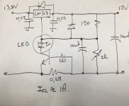
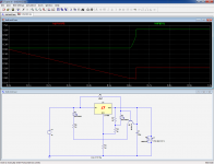
I build the attached circuit. Instead os the LM317 I used a LDO LM1086 regulator. It has the same pinouts, and works a treat.
My question relates to the LED in my circuit. I added it from memory from an old school power supply I built which added an LED in the collector of the transistor to indicate a "current limit" state.
Problem is, that the LED changes the limiting current slightly, and the rate of current limit drastically. The LED also lights up very early, long before the calculated limit value.
Is there a better arrangement that I can use here. I know that the datasheets don't show the LED, but would be awesome to have some form of indication.
Attachments
The idea is good but the problem is that the LED current doesn't turn on hard when limiting. There's always some current through the LED. What you need is an extra 'thing' that turns it on hard when limiting.
Find a point in the circuit that jumps when current limiting, connect that to a transistor 'switch' with the LED in the collector, something like that.
Jan
Find a point in the circuit that jumps when current limiting, connect that to a transistor 'switch' with the LED in the collector, something like that.
Jan
Last edited:
🙄Try it like this, not high tech but might work a bit better.
Mona
LM317 has a specification of 3v min input to output differential
schematic shows 1.8v
15v DC in, to have 12v out, as example
Cheers / Chris
LM317 has a specification of 3v min input to output differential
schematic shows 1.8v
15v DC in, to have 12v out, as example
Cheers / Chris
Chris, I'm usin a LDO regulator of 1,5V. Lm1086.
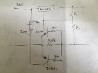
This circuit is a bit more complex, but it will precisely indicate the current limit condition (and it won't create any I*R losses).
A small trimmer may be inserted at the junction of R4 R5 to make sure the threshold is perfectly accurate
The circuit works by comparing the reference voltage of the LT1086 to that of U2 (1.2 V reference). The circuit takes advantage of the fact that the reference voltage of the regulator will collapse once the regulator current limits. This, in turn, trips the comparator, turning on the LED. The circuit doesn't actually measure the output current.
The only thing you'd get from adjusting the R4/R5 ratio is a bit more noise immunity on the over-current indicator - or an LED that's stuck on if you tweak in the wrong direction.
I'd probably increase R1 to a value that allows just the minimum required current to flow in U2 under normal operating conditions. With the current values, I bet the current through U2 wreaks havoc on the line rejection of the regulator.
If you want the LED to turn on at a specific current, you have to measure the current.
Current limiters can be rather tricky to design... You may find some examples in the old National Semiconductor LM317 data sheets.
Tom
Last edited:
I found a solution!!
Except you haven't actually solved anything. 🙂 You may want to re-read Post #2. Or just go implement Elvee's circuit from a few posts back. You may not need fancy references or comparators. I bet a couple of diodes could serve as U2 and a differential pair with a couple of transistors as the comparator. Watch out for temperature effects if you choose to use diodes for the reference voltage.
Tom
Last edited:
Here is a simpler (but less deterministic) version.
R1's value is a tradeoff, and here will cause ~10E-3 error in the divider current.
The LED should compensate the transistor's Vbe to the first order.
Indication won't be as accurate and clearcut as the first version
R1's value is a tradeoff, and here will cause ~10E-3 error in the divider current.
The LED should compensate the transistor's Vbe to the first order.
Indication won't be as accurate and clearcut as the first version
Attachments
@LV, your circuit indicate when the stabiliser starts limiting.
As I understand it the TS wants to limit the current at a value of his choice.
Mona
As I understand it the TS wants to limit the current at a value of his choice.
Mona
This is debatable: I interpreted it the other way round, because the OP wanted a circuit that let him know when "the regulator starts limiting", and also because his circuit showed no means of adjustability of the threshold, and the theoretical threshold was very close to the published limit of the circuit, but I could be wrong.@LV, your circuit indicate when the stabiliser starts limiting.
As I understand it the TS wants to limit the current at a value of his choice.
Mona
Perhaps could diy didi lift the ambiguity?
A side-note: the circuit I have provided will react to any type of loss of regulation, not only current limit: an input brown-out for example.
It could be useful though, if the power transformer is under-dimensioned compared to the regulator for example, which could easily happen since semi's manufacturers sometimes take hefty safety margins over the published limits
It could be useful though, if the power transformer is under-dimensioned compared to the regulator for example, which could easily happen since semi's manufacturers sometimes take hefty safety margins over the published limits
I worry about the transistor in post#10 circuit; it will see more then VEBO if the regulator input is suddenly shorted to ground. Its 200K base resistor limits the reverse current but I think spending another $0.01 for an 1N4149 {the good old Forty Niner} across the emitter base junction, would help me sleep more soundly.
The BE diode of the transistor will always be forward-biased, even in the case of an output short.
It could only become reverse-biased in case the input is shorted with C1 remaining charged, but this would probably kill the regulator chip first.
It could only become reverse-biased in case the input is shorted with C1 remaining charged, but this would probably kill the regulator chip first.
it will see more then VEBO if the regulator input is suddenly shorted to ground.
Starting schematic in post#1 does include the LM317 datasheet's recommended protection diodes that prevent damage when the input is suddenly shorted. Only the follow-on suggestions from readers have omitted those diodes.It could only become reverse-biased in case the input is shorted with C1 remaining charged, but this would probably kill the regulator chip first.
My mistake: I should have read more carefully (or maybe it's time to pay a visit to my optometrist..)
In post 5 the TS : "Chris, I'm usin a LDO regulator of 1,5V. Lm1086."
And the datasheet: "In the LM1086 regulator,
the internal diode between the output and input pins
can withstand microsecond surge currents of 10A to 20A.
With an extremely large output capacitor (≥1000 μF), and
with input instantaneously shorted to ground, the regulator
could be damaged. In this case, an external diode is recommended
between the output and input pins to protect the
regulator."
I see only 100µF on the output, so forget the diode.
Mona
- Status
- Not open for further replies.
- Home
- Amplifiers
- Power Supplies
- Help with LM317 current limit indicator