Just to clarify/correct -
25W RMS at 30% efficiency requires 83W input power or 41.5W per output half (21W on each tranny if pairs used). I was taking the 50% theoretical when assuming 25W (each transistor) for a single pair - just after saying it wasn't that good!
Message is - heatsinks need to be big. Especially for 25W in class A.
Hottest part of the L bracket is of course underneath the transistor. The angle bit refers to the part which attaches to the heatsink, though I'm sure people realise that.
This is a popular circuit but really needs the two potentiometers to have a series resistor to limit the minimum value. This has been commented before (I don't have OldDIY's apparently photographic recall but is buried in this thread somewhere I think).
Thanks for all the help. The L brackets are made of a black coated metal, hopefully alu, and are 3mm thick.
If I don't let the heatsinks get over 100 C the transistors should be in safe operating range, right?
If I don't let the heatsinks get over 100 C the transistors should be in safe operating range, right?
Well I guess 2kg of alu would be nice right now. Thanks for the help everyone, I've got what I need for now I think.
I have built an amp prototype based on 2 1969 boards which are specced at 25w Class A each. The boards are currently listed on ebay similar
The 1969 JLH has an all NPN output stage.
This kit uses MJE15024 an NPN in combination with transistor MJE15025 which is PNP.
Unless the latter is part of a constant current source connected to the positive supply this would depart significantly from the 1969 script.
We would need to see the circuit diagram to see if that is what you have.
Zoea showed a similar picture which shows three TO-3 cans on the L bracket.
I assume one of them is a PSU/ripple filter.That could be the PNP while the other two are NPN. Or the other way around.
I assume one of them is a PSU/ripple filter.That could be the PNP while the other two are NPN. Or the other way around.

I have asked the seller for a circuit diagram to try and figure this out better.
The 2 extra transistors are probably power supply agreed
The 2 extra transistors are probably power supply agreed
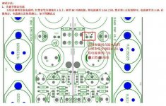
I didn't get a circuit diagram but apparently the circuit is adjusted before shipping. Here is what I have:
Is this the current variable resistor? I am unsure if I can adjust it without having to adjust the other variable resistor too and I'm not too keen on that - but if needs must to lower the temperature I guess it's an option...
Is this the current variable resistor? I am unsure if I can adjust it without having to adjust the other variable resistor too and I'm not too keen on that - but if needs must to lower the temperature I guess it's an option...
Attachments
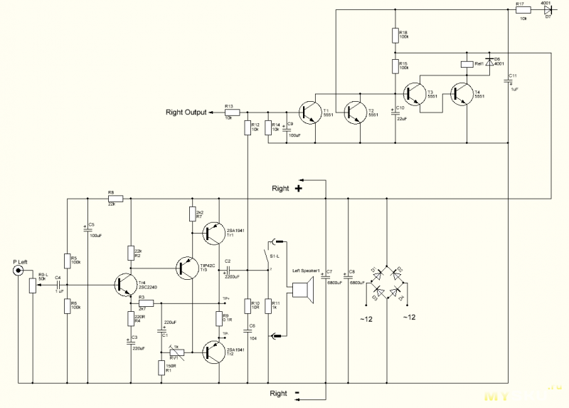
In the circuit shown above the points to measure are the midpoint between the collector of Tr1 and the positive connection of C2 with respect to ground. This should be close to half the rail positive rail voltage. This is shown on the circuit diagram as TP+ Step two is to measure the voltage on the emitter of Tr2 to earth - shown as TP.
The difference between these two point is the voltage drop across R9 and since the resistance of this known you can work out the standing current in the output stage from Ohms law i.e. I=V/R
Following the instructions in Chinese, there is a range of 1-2A that would be adjusted by the 1k trimpot R9.
If you are going to operate at 1A you will need a power transformer rated at 160 VA - a standard off the shelf value with an 18V secondary winding - also a standard off the shelf value.
The next standard values is a 25V winding and probably a jump of of around 500 VA to make best use of the increased potential.
@Zoea - I'm not sure, but the red square you have indicated suggests to me that these are two test pins. I can't identify a trim pot from the layout diagram. A photograph of your board (if you can provide a reasonably good one) would help.
We need to relate the circuit diagram OldDIY has posted to the points on the layout you have shown.
@mjona- I think you meant step 2 should measure the voltage between Tp+ and Tp.
We need to relate the circuit diagram OldDIY has posted to the points on the layout you have shown.
@mjona- I think you meant step 2 should measure the voltage between Tp+ and Tp.
Scheme from another PCB PNP 🙁
This PCB is called HOOD1969 PNP v1.2. Three transistors on the heatsink.
One capacity multiplier.
This PCB is called HOOD1969 PNP v1.2. Three transistors on the heatsink.
One capacity multiplier.
Yes, the circuit you posted might not be the one Zoea has but it might serve as a guide.
Top section probably does not exist in Zoea's (I'm guessing) but as you say will have a cap multiplier.
Top section probably does not exist in Zoea's (I'm guessing) but as you say will have a cap multiplier.
@Zoea - I'm not sure, but the red square you have indicated suggests to me that these are two test pins. I can't identify a trim pot from the layout diagram. A photograph of your board (if you can provide a reasonably good one) would help.
We need to relate the circuit diagram OldDIY has posted to the points on the layout you have shown.
@mjona- I think you meant step 2 should measure the voltage between Tp+ and Tp.
I measure voltages with reference to chassis and use arithmetic to deduce current drop across components. I put the meter black probe into the black binding post hole which should be at earth potential.
That allows quicker and less fiddly spot checks moving the red probe around while watching the meter.
This amplifier is simple and low power however it could be the bottom step on a ladder to a high power project where the supply voltages are lethal. Fiddling about inside a chassis with two hands and probes with an eye on the meter is a juggling exercise which could lead to an unhappy outcome.
PCB #29 has two trimmers. One on the short side of 1/2 U. The other on the long side regulates the current.
True but the setting of R21 in itself does not need to be measured.
Measuring the voltage drop across R9 using two hands and two probes is another ball in the juggling act while twiddling R21 and watching the meter.
The process I use was put to me by one of the present moderators who runs a repair business, he would have been obliged to state the risks of measuring voltage drops across resistors in circuit under power, as I used to do.
Last edited:
- Home
- Design & Build
- Construction Tips
- Help with Hood Class A board (mockup fail)