(I was gonna be a chemist, then I was gonna be an electronics engineer, and I ended up a psychiatric nurse with a degree in accounting - go figure)
That's different 😀
I'm not quite sure how a degree in accounting helps with psychiatric nursing though? 😛
My wife was in hospital last October/November (she had a massive foot infection, and was diagnosed as having become diabetic - she's only just gone back to work last week), anyway I was there one night when a young intern came to see her, so I asked him what Uni he had been to. He said he had a History degree from Oxford!! 😱
To be fair, he then said he was now doing a medical degree at Nottingham Trent University.
FULLY agree with Teemu. 🙂
1) *THAT* is what that tube stage clips like. Period.
2) *THAT* is the *GOOD* distortion, the one transistors, Op Amps and Diodes do NOT give you ... unless expressly designed to do so, that is, in 0.001% of SS amps out there.
Can you say "even harmonics?"
3) all waveforms *drawn* by 99% of Tube Gurus , or present in MB user manuals and such are just fantasy.
Almost nobody cares to hook a scope and see what's really going on.
And if they do, they don't share it with you.
The exceptions are Merlin or Kevin, and maybe a couple more.
Can be counted with the fingers of one hand.
Interestingly, unjustly despised Crate includes waveforms in all schematics, go figure.
PS: R41 *is* a grid stopper.
To be more precise, R41 combined with R42 form a grid stopper with ~330K value. (Impedance wise they are in parallel).
20K in series with it would do very little.
Or if you want to really nitpick, add V2a Rp in series, nominally 68/70K , although it won't cange things that much.
The main point is that besides attenuating signal somewhat, it makes for a better defined clipping point combined with the GK diode, kills highs more when combined with reflected Miller capacitance and does not let C31 charge to such a very high negative voltage, which would change bias and output wave duty cycle too much.
Modifying as little as simple resistor often has much deeper consequences than originally expected.
That's different 😀
I'm not quite sure how a degree in accounting helps with psychiatric nursing though? 😛
My wife was in hospital last October/November (she had a massive foot infection, and was diagnosed as having become diabetic - she's only just gone back to work last week), anyway I was there one night when a young intern came to see her, so I asked him what Uni he had been to. He said he had a History degree from Oxford!! 😱
To be fair, he then said he was now doing a medical degree at Nottingham Trent University.
Happens everywhere.
FWIW I wasn't certain on what Specialty to choose, so I started studying Industrial Engineering, the one which can be applied on most any Industry .
At the same time, started turning my Electronics Hobby into a means of living, and so started making and selling Guitar Amplifiers.
It grew quickly, so I applied for "career change"at the University, they recognized most of what I had studied so far (Calculus, Physics, Chemistry, Statistics, etc.), some was useless (Thermodynamics, Thermal Machines, Hydraulics, "Machines" (mechanical)) , some provided a base (Electricity, Electrical Machines , etc.) *but* I studied only what I needed , mainly Acoustics (way back then it basically meant learning the Leo Beranek book to which I added Olsen's) and the "analog" side of things.
Always *hated* anything Digital so I am still missing those, so formally I do not have a Degree hanging from the wall, although I have 7 full years approved in 3 different Universities.
Almost forgot: changed career once more, some of Industrial Engineering was recognized, and studied one extra year of Business Administration, which was starting to be needed (with up to 15 employees, 2 shops, direct distribution, some exports).
Only thing missing: should have studied Music to complete the curriculum 🙁
what sound you're actually hoping for?.
Do you have a complete schematic you could post?.
Sound? I want like every one else, perfect tone...
 . It just sounds fizzy with uneven distortion. I like a good heavy crunch, to AC/DC. I guess i'm now just looking to improve the tone with some adjustment.
 See post 8 for the best, not perfect schematic I have. Mine is 100w head.
Power amp will smooth things up with asymmetric soft clipping if driven hard enough.
Whoops. Sorry, my bad here. I meant to say symmetric instead of asymmetric.
Because Marshall amps, when we use that term as generic referral, tend to have push-pull output stages.
Generally you can expect push-pull -type amps to clips quite symmetrically whereas single-ended stages tend to have much more asymmetric clipping characteristics.
For example, here's a scope capture of a push-pull tube power amp driven to clipping:

As you may notice, not quite soft, and the grid conduction of the power tubes, and resulting bias shift also generate plenty of crossover distortion. The behaviour is archetypical for many push-pull guitar power amp circuits. Looks bad, right? But this is scope capture of highly praised Trainwreck amps, which heavily rely on power amp clipping to produce distorted tone that actually sounds marvellous.
I bet it doesn't comply with most of the stuff you see written about tubes, softness of clipping, harmonics of clipping, etc. But this is the real deal.
Next in line, scope capture of a single-ended triode power amp clipping:
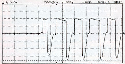
Again, not very soft but the real deal. You can notice how the asymmetric characteristics of tube's different types of clipping behaviours (cutoff and saturation) manifest themselves. Signal swings towards the other halfwave tend to be higher, and due to different kind of clipping process the damping factor also varies greatly accentuating rising signal edges. Transients and even oscillatory ringing is common. You could expect similar performance from other single-ended power amps, like one in Fender Champ, for example.
Again we all know that they don't sound bad when they clip, but they don't sound like clipping push-pull amps either....and despite of abundance of those supposedly "musical" even order harmonics in the signal it probably just sounds like it distorts.
Of course, note that these were just generic examples. Sort of generic behaviour you may expect, sometimes to find that the circuit you are examining tends to be designed a bit differently and behaves a bit differently. But these are the sort of outputs I generally expect to see in overdriven push-pull or single-ended guitar power amps that often recycle the same designs.
The nicely soft clipped sine waves... no I don't see them often. Sometimes, yes. Usually with very mildly overdriven push-pull -type amps, running to resistive loads, without much negative feedback and with tubes that tend to have soft clipping characteristics (not all have). And usually it takes just a bit more overdrive from that point and its almost like square waves again. The "headroom" of that soft clipping region is actually very, very narrow. Here's a scope capture of that same SE amp at milder overdrive, just where it barely begins to distort:
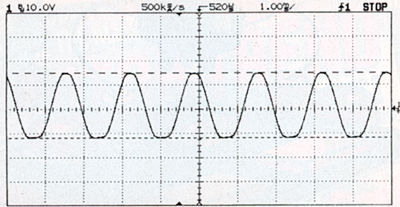
Doesn't take a lot of input signal increase from that point for the clipping to turn very hard.
Last edited:
So I played around for bit last night, I changed the bias a bit on V2B to allow symmetrical clipping which helped a bit.
So after, I started poking around with my scope in the power tube section, I found something odd. The signal was ‘normal’ going to the control grids, but when I looked at the screen grids I seen something odd. There was the normal power supply ripple, the “Camel humps”, but I also seen much lower frequencies and larger amplitude ripple. I never got a chance to check if it was a bad valve or not, but I’m not sure what it is I seen. I did take a video to ask if this is normal.
This was taken on Pin 4 (EL34) at 0.1v per division (10 divisions on the screen) with no signal (the cable was pulled out)
https://www.dropbox.com/s/0d1vr5mnn6s1fea/Grid%20pin%204%200%2C1.mp4
Not sure if that is normal, just the electrons hitting the grid, that is over a volt of ripple.
So I checked the plate, not as bad, the normal saw tooth with a bit of ripple.
Taken at 1v per division on pin 3. I change the speed of the scope to try to give a better view of the ripple
https://www.dropbox.com/s/g87hz8ugm31icva/Plate%20pin%203%201.mp4
I checked my line voltage, but that was rock steady.
- Status
- Not open for further replies.