Hi,
I've built an integrated amp with phono stage using Peter Daniel's Audiosector LM3875 kit. It uses a rotary switch for signal switching and an Alps blue pot for volume control. I've got it working and sounding great (phono now works thanks to some help from this forum).
However - I have a Boozehound Labs JFET Buffer stage board sitting in my case, and I want to put it in the signal path to hear how it affects the sound. I've been playing with placing it after the pot, but can't get rid of the hum. I'm sure that I have a grounding scheme issue when I put the Buffer into the mix.
Here is a general description of my working integrated amplifier circuit:
Signal Scheme
- 4 RCA inputs
- 3 pairs of inputs send signal to rotary switch --> common pot --> LM3875 input
- Signal ground from the 3 pairs of inputs above to SG pad on LM3875 PCB
- 1 pair of inputs send signal to RIAA preamp PCB (http://cdn.shopify.com/s/files/1/0289/4153/files/Boozhound_Laboratories_JFET_Phono_Preamp.pdf?33) --> rotary switch --> common pot --> LM3875 input
Signal Grounding Scheme
- 4 RCA input grounds
- 3 pairs have each L and R channel signal grounds connected and sent directly to SG pad on LM3875 PCB
- 1 pair has grounds separated and sent to RIAA preamp PCB. Bottom of PCB is a grounding plan. 1 ground wire from PCB is sent to star ground (not SG on board) and this results in a fairly quiet configuration.
All power grounds go to common star. I'm using +24V regulated DC to power both RIAA and Buffer PCBs.
This is the buffer I'm trying to integrate: (JFET Buffer kit – Boozhound Laboratories)
My thinking is that I might not understand the signal ground return path properly and that maybe I'm creating a loop. I would have thought that I can run the signal ground from the RCAs directly to SG on the amp, and pass the signal itself through the various stages (switch, pot, buffer, amp). Maybe there is an interaction with the pot and buffer ground? Any thoughts are appreciated.
Martin
This is a really hard question, that no one is going to be able to answer easily, especially as we don't know the grounding scheme of the added part. There are so many possibilities, and since you already appreciate that problems can exist you are a step ahead already.
Ground planes tend not to be great things for signals, but probably are good for bypass caps and so on.
A pcb layout would help, with a schematic, but I fear that you are probably going to have to do some reading (here being one of the good places) if you arer going to see how it all pertains to you.
That's kind of what I thought...
The circuit is shown in the link posted above - that's the best I've got.
Have done a bunch of reading already, and tried numerous grounding schemes. I'll certainly keep reading.
Cheers.
The circuit is shown in the link posted above - that's the best I've got.
Have done a bunch of reading already, and tried numerous grounding schemes. I'll certainly keep reading.
Cheers.
Member
Joined 2009
Paid Member
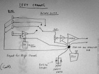
You might get more help here if you could post a diagram. I've drawn up what I think you have built and I've included an earth-loop interruptor between your signal ground and the safety ground of the chassis - you likely need one if you don't have one already.
You could also try the JFET bugger with an independent power supply outside the chasis and before the signal reaches the RCA inputs - to see if it generates hum by itself without changing anything inside your integrated amp.
You could also try the JFET bugger with an independent power supply outside the chasis and before the signal reaches the RCA inputs - to see if it generates hum by itself without changing anything inside your integrated amp.
Attachments
In my opinion you need a buffer if the Source is incapable of driving the combined load of the interconnect cable and the Receiver.
Why do you think you need a buffer inside the Receiver?
Why do you think you need a buffer inside the Receiver?
- Home
- Amplifiers
- Chip Amps
- Help With Grounding for JFET Buffer with LM3875