Hello everyone,
I came accross this forum almost by accident a few weeks ago. I was surprised to find the following the LM38XX amplifiers have. I thought they would have sounded like a radio shack alarm clock.
My NAD751 recently went t**s up so now I'm looking for an amp to replace it. As I used it primarily (almost exclusively) for music I figured a chipamp might fit the bill. My speakers are B&W DM602s which are bi-ampable so I think I'd like to try biamping them with a pair of chipamps each. I expect the advantages of biamp won't be as great in this case since they will still be going through the speaker crossovers and not crossed over before the amp.
So here is what I would like to know about building my first chipamps:
I was thinking of buying the chipamp.com kits. They seem fine to me, are there any issues with the kits? I'm sure I could not design and fab (professional PCB fab that is) a system cheaper, especially considering my time. Are there any other sources fro chipamp kits?
What do I use for volume control? I will be using the amps with a CD player, and possibly MP3 player but no phono. Do I need a preamp? Or can I simply feed the line outs through a stepped attenuator then into the amps? Where is a good place to get the stepped attenuators? What impedance should I use?
Where can I find the toroidal power transformers for a decent price? What is the reccomended secondary voltage for 8ohm speakers?
Are there any advantages of using parallel amplifiers for moderate listening levels? About the loudest I'd go in my house is turning my 35W (100+ peak) NAD304 up halfway.
How can I expect the chipamp performance to compare with my NAD304? If I do end up building a chipamp I'll probably do some back to back tests.
Any and all feedback is welcome. Feel free to get technical. I am an electrical engineer, though most of my experience is with embedded systems. I find it interesting to look at some of the PCB designs, its a bit of a change from all the 4layer 7mil feature size PCBs I've designed.
The first thing you should do is measure the voltage output of the transformer in your NAD. I suspect this may be suitable to power your chip amps. Voltage rails up to around +/-37 volts will be fine for 8 ohm loads so you want a transformer with a maximum output of 25 VAC.
Not only could you use the transformer but the case as well!
The chipamp.com kits are fine. And bi-amping (even with the existing passive crossovers) won't do any harm!
You may or may not need an active buffer stage or pre amp between your CD and the chip amps.
I would be very surprised if the chip amps didn't sound better than the NAD.
May I suggest that you do as much research on this forum as you can as all of your questions have been answered somewhere. Also this site and the others on the Gainclone ring link will provide you with all the information you need to complete your project. 😉
Yeah.. the first time I read about gainclones 4 months ago I thought exactly the same thing, until reading reviews and forums. Now I have a 4-channel gainclones driving a pair of speakers actively and not sure how to top the quality 😎
I had thought about taking the transformer from the NAD. There are two reason why I don't want to do this. First of all there the power section of the NAD still works. if I buy a new receiver I may just patch it into the NAD power section. Secondly the NAD uses a standard (non-toroidal) transformer. I was always under the impression that toroidal transformers are better. Is this true?
Just because a transformer is a toroid doesn't mean it's good! There are lots of good transformers that aren't toroids, probably including the one in your NAD receiver.
drproton said:I had thought about taking the transformer from the NAD. There are two reason why I don't want to do this. First of all there the power section of the NAD still works. if I buy a new receiver I may just patch it into the NAD power section. Secondly the NAD uses a standard (non-toroidal) transformer. I was always under the impression that toroidal transformers are better. Is this true?
Hi drproton,
I think that the ONLY (electrical) way that toroidal transformers are better than other transformer types is that they have relatively lower-strength radiated EM fields, which are also concentrated basically around only one axis. Toroidals are usually worse than E-I types at filtering garbage out of the AC mains, for example.
Maybe you could just leave the entire NAD power supply completely intact, and use it for your chipamps! What existing DC rail voltages does it have?
Thats not a bad idea. There is one other problem with the NAD transformer. It won't fit in the enclosure I want to use. I've done some more research. It seems like (anecdotally at least) preamp/buffering the chipamps give better quality sound. I would guess this is due to impedance issues, and higher level outputs like headphone outs or sound card outs don't suffer the same. Now that I think of it my NAD 304 has separable preamp/poweramp sections. I can use this to test the preamp thing. As a test I can also use my bench supply which is capable of +/- 50v @ 5A. I'd still run this through the power supply caps as this supply is a switching type and might be prone to noise.
I found a couple preamp designs in my searching, but the only ones I found that are available as a kits are the twisted pear amps. I these okay? Are there any other kits out there? How about kits for active crossovers?
What does the term "balanced" mean as it pertains to audio? I know I learned this one before, but I can't remember it now.
drproton said:What does the term "balanced" mean as it pertains to audio?
Balanced means you have two signals (one non-inverted and one inverted) and a ground.
That was my guess, seeing as how "balanced" sources are used to feed bridged amps.
On another note, I fixed my NAD 751. It turns out the root of all the problems was, quite typically, a defective electrolytic cap. Once I saw that the line marked "DC8V" was about 6volts DC + about 6V of sawtooth I tracked it back and found a slightly bulged cap. I replaced that and everything was good.
I think I will still build the gainclone. I'm also probably going to make a set of speakers for my computer. The ones hooked up to it now cost me $0 and sure sound like it.
no,BWRX said:
Balanced means you have two signals (one non-inverted and one inverted) and a ground.
balanced = same impedance on both the inverting and non-inverting inputs.
Same impedance implies the same resistances and the same reactances.
Andrew, technically you are right that the impedances should be the same in order for the best performance from both balanced drivers and balanced receivers.
The main purpose of balanced circuitry is to reduce any noise picked by or radiated into the input wiring. Rod Elliot explains it briefly here: http://sound.westhost.com/impedanc.htm#balun
The main purpose of balanced circuitry is to reduce any noise picked by or radiated into the input wiring. Rod Elliot explains it briefly here: http://sound.westhost.com/impedanc.htm#balun
Well, I just took the plunge and ordered two stereo kits from chipamp. To power these I was thinking of using this hammond xfmr:
http://canada.newark.com/95B5029/power-products/product.us0?sku=HAMMOND-182P22&_requestid=78867
For my work we get a pretty good discount from newark so I will be able to get this a bit cheaper yet. Is this a suitable part? Will it be powerful enough to run four chipamps? Based on simple power in vs power out it should be enough at 8 ohms. As this will be a biamp configuration I expect the tweeter amps won't be working all that hard.
Are they any nice and cheap commercial chassis out there? I was thinking of building my own from some aluminum. It would be mostly 1/16" or 1/8" construction except for the sides which would be 1/2" Al bars for heatsinking. How about garolite? Its cheap, light, and strong but doesn't provide any RF shielding.
For those that don't know garolite is basically PCBs with no copper.
Just as you mentioned, that transformer should be fine for 4 chip amps, especially if two amps will be powering tweeters.
I've got everything put together now and my chipamp is making music. However there is a problem. With no input connected the speakers are dead silent. When I plug in the cable to the pre-outs of my receiver a loud hum comes from the speakers. It seems to play just fine, just over top of a heavy hum. What might be the cause of the hum? Do I need a cap at the input?
I'm using the chipamp kits. I put everything in the case and connected all 4 (I made a 4-channel amp) chassis grounds from the amplifier PCBs to 1 point. I also connected the AC line ground to that point. The only potential ground loop is that the IEC filter module I used has a metal case in contact with the chassis. The common ground point is a couple inches away from this. The chassis is made from aluminum plate so I doubt any voltage drop is possible.
When I connect a portable source (ipod) there is very little hum. The hum that is present is probably just the noise from the source being amplified. Can anyone help?
the loops from the 4 interconnect shields entering the amp and the possible connection to Safety Earth of the various sources and your power amp.drproton said:I put everything in the case and connected all 4 (I made a 4-channel amp) chassis grounds from the amplifier PCBs to 1 point. I also connected the AC line ground to that point. The only potential ground loop is ............
When you say AC line ground, do you mean Safety Earth?
Yes, I do mean the safety earth. Would it work if I let the low voltage stuff float, i.e. disconnect the grounds from the amp PCBs?
With only the ground connected from the interconnects there is no buzz. With one channel connected only that channel will buzz.
With only the ground connected from the interconnects there is no buzz. With one channel connected only that channel will buzz.
I rearranged the grounding some now the hum is down to an acceptable level, about the same as my other amps.
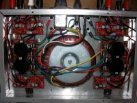
Instead of 1 start point I connected the grounds to 1 heatsink bar. This bar is a 12" x 2" x 1/2" piece of solid Al. The grounds are connected within about 3" of each other. Not sure why this made such a big difference, but all is well now. Maybe I had the ground wires is exactly the wrong spot and was getting induction.
The amps sounds pretty sweet, clear throughout the entire range with nice tight bass. I think it sounds better than the power section on my NAD751 receiver, I'm feeding the amp from the pre-outs of the receiver.
[EDIT:] I just saw that you have already greatly-reduced the hum level. I'll post this anyway. Maybe you can get the hum down to 'inaudible', if you keep trying for just a little longer.
Also, can you give any more details about exactly what you did, that reduced the hum so significantly? i.e. Do you have several 'heatsink bars'? And did you connect ALL of the grounds to just one of them? Are all of the heatsinks connected to the chassis? Are all of the chips well-insulated from their heatsinks? Is it possible that there's a bad ground connection related to the amp that uses the heatsink to which you connected all of the grounds. i.e. Do you get the same result if you connect all of the grounds to any one of the other heatsinks?
I guess I'm wondering if your solution is actually just 'masking' the original problem. I'm not quite sure how to tell, at this point. Someone else should have a much better idea.
But, for now, with a foggy brain today for some reason that I will not admit to, except to say that it was not illegal, all I can think of is to maybe try 'shotgunning' it; maybe something like the following: Use an ohmmeter (with all power disconnected) and measure heatsink-to-chassis resistance (and heatsink to star ground), for each heatsink (possibly looking for only a small difference; I'm not really sure if it might be noticeable or not, in that case.). And maybe try similarly measuring the resistance from each PCB's ground(s) (especially where the signal input grounds connect, and maybe then also at the chipamps' inputs' ground points) to the star ground, and to the chassis. I'm guessing that at least some of those measurements should also be done with all or some of the grounds disconnected from the star ground point/heatsink, e.g. the 'to chassis' ones. Maybe alternatively, if you have an oscilloscope, you could use a low-attenuation vertical setting and probably mainly probe the signal ground connections on the PCBS (and maybe also the chipamps' feedback dividers' ground points), while connecting the probe ground to various points, such as the star ground, and the signal ground entry points (or maybe even their source ends). It might be possible to do something similar with an AC voltmeter, if it could reliably show differences between low-level AC measurements.
On another note: Since you mentioned that you also re-positioned some wires, can you still get a comparable hum level by rearranging any wiring? If so, that might eliminate the need for trying to find another fault (e.g. per my babbling, above).
----- My 'original' post:
I'm glad to hear that you 'took the plunge'.
I am not familiar with those kits, by the way. So I don't know what type of grounding scheme they provide for.
Where do you connect the "grounds" of the signal input cables?
I think that the signal input grounds' conductors should connect only to the audio grounds, i.e. only on the(ir) amplifier PCBs, and, actually, only directly to the point that serves as the chipamp input pin's voltage reference, i.e. where the input-to-ground resistor and the feedback-divider-to-ground resistor are first connected to each other.
The signal input "grounds" should not even be considered to be grounds. They are just the reference voltages for the inputs with which they are paired.
You will need to make sure that any signal input connectors are insulated from the case, so that their "grounds" are not inadvertently connected to a case or chassis or whatever, where they enter.
Isn't there more than one ground return conductor from each amplifier PCB?? (It seems like there should at least be separate power and signal grounds.)
Have you tried using 'disconnect networks', between the amplifier PCBs' grounds and the safety/earth/chassis ground? They usually consist of a small resistor (say 10 Ohms or more) in parallel with either two hefty inverse-parallel diodes or a hefty rectifier bridge, usually in parallel with a small capacitor of maybe 0.1 uF (I'm not sure if it needs to be the AC-mains-safety-rated type; couldn't hurt if it was, I guess. Maybe AndrewT will enlighten us, on that.)
-----
P.S. ALL conductors develop SOME non-zero voltage drop, for any non-zero current.
P.P.S. (Just because I like this quote: ) Current does not follow the path of least resistance. It follows ALL paths, in inverse proportion to their resistances.
- Status
- Not open for further replies.
- Home
- Amplifiers
- Chip Amps
- Help with first GC project