Folks, I bought a Sepparo SE88I a while ago and found it had been a bit modified, I replaced a couple of suspect Russian Paper in Oil capacitors and the amp has been working fine until recently. It stopped working with a lot of distortion and crackling. I took a look around inside to find the capacitors on the KT88s Cathodes were seriously bulged. I replaced these however the amp was still not working with lots of hum and distortion regardless of how the triode or feedback switches were set.
Now I can work a soldering iron but the maths of electronics are beyond me. I decided to have a poke around to check the values of various components against the circuit diagram I have. Apart from the switches there are a number of values different from the those shown on the diagram in the attached PDF.
I would really appreciate it if you could give me a bit of help in deciding what to do with the amp. Should I revert to the component values in the diagram or are the values currently OK?
Is it likely the valves are damaged given the component values and the switched?
Really any help to fix this amp and any insight as to why the components may have been changed would really be appreciated.
Thanks
AVO111
Attachments
It looks that the 390k is instead a dead short? In which case it definitely needs replacement.
As the 820R is instead 820k? That's a huge difference but I'm not sure if that's a typo, someone else may be able to comment.
The 470u capacitor is definitely suspect, probably leaking like mad and high ESR if it is rated 470 and measuring at half.
The others are probably close enough to not really matter.
Last edited:
Hi, The 470Ω resistor has had a couple of 1.5K strapped across it and the capacitor in the 470uf position is a 330 with a smaller cap strapped across it to give the measured value. It is these last two components that I replaced as they were blown, like with like without consulting the diagram. Someone has deliberately made these changes I was hoping someone could suggest why🙂
The first thing I notice is that the KT88 control grid stopper resistor is 10k Ohms, and the control grid resistor to Ground is 560k Ohms. 560k + 10k
That is a total of 570k Ohms from the control grid to ground.
The original Genalex KT88 data sheet says use a maximum resistance from control grid to ground of 220k for self biased mode (you are using self bias mode).
Genalex were Robust tubes, could take lots of punishment.
Modern tubes often do not live up to the older KT88s.
Even the best of KT88 tubes do not like more than 220k there.
Some modern KT88 tubes have to have even less than 220k there.
So what has happened is that your KT88 tubes have gone into thermal runaway.
The control grid starts to draw grid current, the voltage there goes positive, that causes the current to go even higher, and on and on.
Then as the tubes drew lots of extra current, the voltage across the self bias resistor goes up and up. That new higher voltage exceeds the the cathode caps maximum voltage rating. That causes the capacitors to Bulge.
There may, or may not, be other problems with your amp, but that needs to be taken care of right now.
The cathode from the tube that drives the KT88 should easily be able to drive a KT88 resistor that is more like 180k, instead of the 560k that is there.
Of course that will change the phase at low frequencies, so the coupling cap might have to be increased (if the negative feedback can not deal with that phase change, just increase the capacitor by 560/180 = 3X the capacitance).
A 6550 that some tube rollers stick in that KT88 socket has to have the control grid resistor no more than 100k Ohms in your amp.
Perhaps someone tube rolled with 6550s before you got the amp, and the result was the bulged caps.
Sometimes if you exceed the tubes maximum ratings, you are better off going to Las Vegas and taking your chances.
And we know who wins at Las Vegas, they are still there in thriving businesses.
Last edited:
Thanks for the analysis. According to the schematic the grid stopper and control grid resistor are stock values. Would the KT88s not have red plated if they were being seriously over cooked? I am sure that did not happen, the amp was running in my office for a couple of years 8 hours a day so I would have expected to see that if it had happened. Is there an easy way to find out if the KT88s are goosed?
So I had a look at a bunch of other KT88 schematics and most do have 220K or less however I did have 2 examples where 470K was used as the control resistor one with and one without a stopper. What value of resistor should I use in parallel with the 570 to get to 220 or there about?
Just to be clear the capacitor I need to change is the one connecting to the screen, currently.56uF and shows as .47uF on the original schematic. I would need a 1.5uF 630V for that?
Thanks!
I would just replace the components with correct values, rather than bodging components in parallel
What value of resistor should I use in parallel with the 570 to get to 220 or there about?
Just to be clear the capacitor I need to change is the one connecting to the screen, currently.56uF and shows as .47uF on the original schematic. I would need a 1.5uF 630V for that?
Thanks!
From interest, was it a kit or factory assembled before it was modified?. If it uses a printed circuit board I can understand your reluctance to remove and replace components. Look into solder temps and use of pumps, flux and braid. Also, toothbrush and isopropyl alcohol to clean the PCB afterward.
1. Use 330k in parallel with 570k (~200k), or either 180k/220k as direct replacement. Replace the 0.56uF cap with 0.22uF/630V (its cheap and to be safe).
2. At least confirm: '390m' is 390k, and '820k' is 800 ohm, preferably change back to original values as per schematic.
3. Change KT88 cathode resistor back to original value.
4. Measure the resistors (properly) before soldering them in.
5. Replace the KT88 bulged cathode resistor bypass capacitors with something decent, making sure they're rated for appropriate voltage and observe polarity when fitting.
6. Connect it up, power ON and hit play: you'll soon know if your KT88s are 'goosed' 🙂
If you wanted to (I would) reduce the 15k grid stopper on the input tube to 1k5, and reduce the 15k grid stopper on the KT88 grid to 2k2.
HK
Last edited:
Schematic looks like a typical chinese internet whiz with weird obsessions designed it.
I'd tear the damned thing tottally apart and build something the right way.
I'd tear the damned thing tottally apart and build something the right way.
If it were mine I'd bung it on a lamp limiter or dim bulb after checking the OPT hasn't shorted then take some voltage readings, first HT/B+ but in particular g1 to ground, then g1 to cathode. we want to 0v on all grids in respect to ground then around 1-2v for ECC83's, 8v ish for ECC82's/6SN7's and 40v ish for the OP valves for g1 to cathode.
All this tells us things are reasonably ok, it'd then be a case of putting a signal in one end and following it through each stage, for that you need a scope but Soundcard Scope a free PC based scope will do with a homebrew test lead.
Andy.
All this tells us things are reasonably ok, it'd then be a case of putting a signal in one end and following it through each stage, for that you need a scope but Soundcard Scope a free PC based scope will do with a homebrew test lead.
Andy.
WARNING: VOLTAGE UP TO 500V EXISTS WITHIN CHASSIS WHEN POWERED ON.
CAUTION: VOLTAGE EXISTS WITHIN CHASSIS FOR AN UNDETERMINED PERIOD OF TIME AFTER SHUT DOWN.
NOTE: Check for voltage across caps before doing anything.
CAUTION: VOLTAGE EXISTS WITHIN CHASSIS FOR AN UNDETERMINED PERIOD OF TIME AFTER SHUT DOWN.
NOTE: Check for voltage across caps before doing anything.
Last edited:
Great folks, lots of useful stuff and something to keep me busy over the weekend!
The history of the amp is that it is a Chinese amp however the previous owner has done a lot of fiddling around. As mentioned it did have some weird Russian PIO capacitors that I replaced with normal audio grade at the same values. At that point I didn't go through and check the other values in retrospect I should have done a proper number on it then. After that I ran it in my office for a couple of years, the sound was OK but not as good as my other valve amp which is a Chinese kit EL34 SE which has now also failed, I suspect the rectifier valve is gone as it was blowing input fuses regularly and last time I powered it up there was a nice firework display of arcing inside that tube!
Hanze yes I will be carefulI have some experience inside these things and a bit poking around in live 3 phase mains supplies so I will be very careful!
Cheres folks!
Some really odd value choices there.
DC voltage checks are a primary tool for sick electronics. Here is my rough guess what to expect. Any reading way-wrong is probably telling you something. Slightly-"wrong" numbers may be my dumb guess, my slop, the changes in values, or tube tolerance. Grid "0V" can be a half-Volt off on little grids, couple-Volts off on the big KT88 grid, but you really want the '88 grid idling at less than a Volt.
...the maths of electronics are beyond me....
DC voltage checks are a primary tool for sick electronics. Here is my rough guess what to expect. Any reading way-wrong is probably telling you something. Slightly-"wrong" numbers may be my dumb guess, my slop, the changes in values, or tube tolerance. Grid "0V" can be a half-Volt off on little grids, couple-Volts off on the big KT88 grid, but you really want the '88 grid idling at less than a Volt.
Attachments

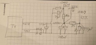
OK so as I don't have any of the values of component to make proposed changes , I have been poking around with my trusty meter. most measurements are as per PRRs diagram. the major differences are the supply to the 12AU7. The anode voltage is 201V and the cathode voltage to the coupling capacitor 97V. The grid voltage at the KT88 is 1.6V with no signal.
I have traced through the power supply and the arrangement is somewhat different from the schematic. The diode that is shown as a 200V zenner across the supply to the Anodes of the 12AX7 seems to be across the supply to the 12AU7. It does measure 200V across it. This would explain the low voltage at the anode and the low output at the cathode to the coupling capacitor.
The wiring is fairly easy to follow, black is ground orange is supply volts and yellow is heaters
So what do I do next? Should I lift the diode? If so what other changes would I need to compensate for the anticipated increased voltage into the coupling capacitor?
I will need to do an order for parts and want to get useful bits!
Thanks!
Attachments

I took a look around inside to find the capacitors on the KT88s Cathodes were seriously bulged.
So I think that the voltage across them went above 63v. So either the 470r went high value or the KT88 have red plated.
So I think that the voltage across them went above 63v. So either the 470r went high value or the KT88 have red plated.
When an amp works for years, and then goes bad, there are multiple causes.
One of them is:
As tubes age, they can become gassy.
The grid starts to have current, and they can go Positive.
When you have a KT88 with a grid resistor of 560K, the grid voltage goes much higher than when the grid resistor is 100k.
As the grid goes more positive, the cathode current goes up, the tube heats up, the grid becomes even more positive, and on and on.
The main reason of a cathode resistor going high resistance is too much current and too much voltage (too much power), versus the power rating of the resistor.
As the cathode current goes up, the voltage goes up (even if the resistor is not destroyed), and then the bypass cap takes the blow (too much voltage, and . . . Bulge).
Even if you get the amp working again, if you do not correct the KT88 grid resistor, you may have to fix the amp again.
A car with a 7,000 RPM redline can be driven at 8,000 RPM, but how long before it needs repair?
And depending on the KT88, the cathode bypass cap voltage rating, you may not have to red-plate the tube to get thermal runaway.
OK, I agree the grid resistor needs changed. What else should i change to make this amp work properly? Is my guess that the power supply diode is incorrectly positioned, if I fix that the voltage will go up at the Anode. Is it possible that the grid resistor value is high because the anode voltage is too low? I am struggling a bit because I really don't get the maths to figure out the values and I would rather not trash the amp or anything else like a set of KT88s assuming the existing ones are cooked!
Thanks for the help!
Thanks for the help!
I guess the grid resistor was high to make the coupling cap lower value. When you drop the resistor the cap need to increase accordingly to pass the LF.
I think there is ample drive but would have to check on LT spice.
- Actually even with 100K its 3.3Hz. Why is the cap so big then?
I would also suggest if you don't replace the .47uF with the KT88 not plugged in you do get 0v on the grid.
LT spice indicates over +/- 100v drive into 100k load.
I think there is ample drive but would have to check on LT spice.
- Actually even with 100K its 3.3Hz. Why is the cap so big then?
I would also suggest if you don't replace the .47uF with the KT88 not plugged in you do get 0v on the grid.
LT spice indicates over +/- 100v drive into 100k load.
Last edited:

Just need to check the valve below the 12au7 it is 12au7 not 12ax7? If its 12ax7 there won't be enough current.
Looking at the layout its probably the 12ax7 in which case why does the schematic show 5v across the 5k6.
Confused!
Last edited:
A 0.047 Uf cap along with a 330K grid to ground resistor is PLENTY for low frequency.
No one that I know, human, can or need to hear a frequency of 3.3 hertz.
Whoever designed that miserable amp is some kind of nut case with obsessive values in mind.
All those smaller caps paralleled across the filter caps are nonsense too.
This only shows me this so-called designer was fed internet garbage, like so many others are.
- Home
- Amplifiers
- Tubes / Valves
- Help with dodgy modded amp!