You've 'gotta keep notes 🙂
C530. That tells us what we already suspected that the problem is (and it has to be) to the left of C530. So with C530 refitted we continue.
C518. This is where we have to be very very sure.
C518 removed and no popping means that the problem seems to lie to the left of C518.
To be 100% sure C518 isn't at fault we have to substitute it by removing it completely and fitting either a new part or perhaps swapping with C517 which we know is on the good channel. Recheck the polarity too just to be sure. There must be no doubt whatsoever at this point.
Now it goes one of two ways... either it is still faulty or not.
Assuming it is still faulty we have to absolutely assure ourselves again that the problem is only present when C518 is fitted (which we know is good because we swapped it 🙂).
So this is where is gets interesting...
The DC voltages on Q504 (and all the transistors) differ a little from those in the manual. That's absolutely normal. The supply voltages could be slightly different and there are component tolerances etc. As a technician I have seen so many manuals where the voltages quoted are just plain wrong so no problems there at all, however 🙂 that doesn't rule out microscopic changes in DC conditions occuring rapidly due to a poor/faulty transistor.
Before we reach that point we can be sure... yes 🙂, that with C518 removed it's silent, and with C518 fitted the noise is present.
If we have reached this point it is possible it could be a transistor issue.
C506. With it removed the input the input to the preamp is "open" or "floating" and very sensitive to stray pickup. That's what the hum and noise is. That's normal.
So as we did before we must "short" the input to ground via a cap. This is where we reconnected C506 to ground (post #66)
http://www.diyaudio.com/forums/solid-state/202909-help-dc-volume-pot-4.html#post2838231
If it still pops now then we are looking at a problem around Q502 and 503... maybe the transistors, maybe not. Lets see what all this proves.
This is getting weirder and weirder...
C518 removed-without any doubt there is no popping
C518 substituted with another brand new 4,7uF 50V cap and installed I get popping again, polarity checked against marking on the silkscreen and the photos of the old cap in place before recapping, no doubt here as well.
I am absolutely sure that with C518 removed channel is silent, and with C518 fitted the noise is present.
C506 was removed (minus leg desoldered) during the above tests.
Than I used a piece of wire to connect minus leg of the cap with ground side of R516, hum is now gone. But not only hum, there is no popping and also there is no scratchiness while rotating bare volume pot.
As for Q504 I don't think its faulty per se, since it was changed, but rather circuit around him.
Interesting findings, don't you think? And we were so close two weeks ago, if only I had tried on speakers when that C506 was shorted to the ground.🙁
Interesting indeed 🙂 you know where this is leading back to don't you !
C518 removed and no popping is good enough for me.
C518 refitted and popping noise is back. Polarity checked visually, thats 99.999% good enough... make it 100% by measuring DC volts across it and seeing it conforms to the way it's fitted. Of course it does 🙂
So we are sure then, C518 fitted and is a known good part and popping noise is present.
On to C506... what is that telling us ?
With it's minus leg to ground we have a guaranteed "no signal" condition. And the noise has gone... yes ? 100% sure ?????
If you are OK up to this point then we seem to be back to the volume control that was swapped. Perhaps this really is picking up some stray noise/hum of some kind.
If so we can try and prove it perhaps but we must be 100% sure that the noise has gone with C506 grounded.
Interesting indeed 🙂 you know where this is leading back to don't you !
C518 removed and no popping is good enough for me.
C518 refitted and popping noise is back. Polarity checked visually, thats 99.999% good enough... make it 100% by measuring DC volts across it and seeing it conforms to the way it's fitted. Of course it does 🙂
So we are sure then, C518 fitted and is a known good part and popping noise is present.
On to C506... what is that telling us ?
With it's minus leg to ground we have a guaranteed "no signal" condition. And the noise has gone... yes ? 100% sure ?????
If you are OK up to this point then we seem to be back to the volume control that was swapped. Perhaps this really is picking up some stray noise/hum of some kind.
If so we can try and prove it perhaps but we must be 100% sure that the noise has gone with C506 grounded.
I know where this is leading but I cant say I like it🙂
C518 - with black probe on the minus leg of the cap and the red probe on plus leg I get a reading of 1.4mV DC with NO minus in front of the value, so correct polarity of C518 is established with 100% certainty.
With C506 shorted to the ground amp is silent as a class D😀 100% sure
The reason why I have trouble parting with the new pot is numerous:
a.) It was the biggest sonic upgrade in my amp, for the first time I had perfect tracking between channels and that was a pleasure to listen to. Since it is not stepped it was easier to find that sweet spot of perfect loudness than with the old one, I never listen past 2 on the scale of 1-10, because that is pretty loud already with not so sensitive speakers at 90dB.
b.) price was 30 pounds
But if it has to go, so be it.
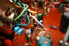
And now one more of my crazy theories. Is it possible that noise is picked by one of the wires entering the pot, and not the pot itself. What if the same component that is producing pop is at the same time noisy, micro-phonic and is transferring noise in that white wire going to the pot above it. If you look at the picture white wire which is originating in "red area" ( those two transistors are Q504 and Q502) going to the pot signal out pin. Since it makes twisted pair with the yellow wire, the noise is transferred to the other channel but lower in intensity. I am probably talking rubbish here, but brain storming is good🙂
Attachments
It is looking like the pot or wiring.
C506 to ground proves the "problem" is entering the preamp input.
The wiring isn't a crazy theory at all, it probably is something like this causing the issue.
It's a little difficult for me to take the exact wiring in from a picture... it makes sense to you because you see the full picture and know how it all connected 🙂 Without seeing for real how the original looked and was wired I can't say...
But yes, it looks like a problem in that area.
It might be worth trying a normal (cheap but good pot) wired one step at a time... or we can do that with your pot fitted if you want.
Having proved the amp silent with C506 grounded... yes 🙂 sure yes 🙂 we can carry that forward wiring the pot one lead at a time.
C518.... it's got to be right. How do you get 1.4mv across it ? With the amp on there should be around 15 volts.
Does that make sense ?
We can now try and wire the pot one step at a time and see where the problem occurs.
We can now try and wire the pot one step at a time and see where the problem occurs.
Does that make sense ?
We can now try and wire the pot one step at a time and see where the problem occurs.
I am willing to use either, new tdk or old original, it is your call.
Can you please elaborate on wiring one step at a time, I presume earth is kept connected and then we remove one wire at a time, beginning from input or output? C506 connected while testing?
Those 1.5mV across C518 isn't that normal, I thought no DC should be present at all across cap, so a small reading is OK?
Lets use the new pot... if we get nowhere with that then we try the original.
This C518. The collector of Q504 has around 15 volts on it. That will be the positive end of C518. The other end of C518 goes to R530. That should be at zero volts DC. So measuring across C518 should show about 15 volts (or whatever the collector volts actually is). 🙂
Remember the wiring and the way the pot looks is all familiar to you, it isn't to me so we do it one step at a time and test along the way. I am looking at the board layout in post #11 for this. You probably think that it is all wired like this anyway but lets do it from scratch and test.
Make sure you understand the logic in this before wiring it up 🙂 We will work on ONE channel at a time so first connect C505 (left hand leg on diagram) back to ground so as to keep this channel silent. Now we work on the other channel.
1. First unsolder all the wires to the pot and unsolder them all from the PCB (for both channels).
2. Now take one wire and solder it to the correct ground point on the PCB marked E7 on the board.
It is possible that the wiring routing and layout is important for all these connections. This procedure should help prove that.
3. Connect that wire to the two end ground pins on the pot.
4. Now connect a wire from the C506 terminal on the PCB (make sure C506 is soldered in properly now) and route it correctly to the pot.
At this stage we are going to test again and so now connect this wire temporarily to the pot ground pins instead of the middle pin.
5. Switch on and test. It should be silent when switch is operated as we are in exactly the same electrical configuration as when we tested earlier by isolating C506 and connecting it to ground at the PCB.
If it is silent switch OFF and transfer the wire over to the middle leg (wiper) on the pot. We will say to use the channel of the pot nearest the chassis.
Retest... it should be silent with the volume control on minimum.
If that is OK then we wire up the other channel exactly the same, reconnecting C505 correctly and running a wire from C505's terminal on the PCB to the middle leg of the other channel on the pot.
Retest... both channels should be silent.
Lets see where it fall down doing this... it may be picking up noise on the wires to the pot or the pot may in some way be coupling to the chassis. We could only eliminate that by swapping back to the original pot.
So lets see 🙂
Lets use the new pot... if we get nowhere with that then we try the original.
This C518. The collector of Q504 has around 15 volts on it. That will be the positive end of C518. The other end of C518 goes to R530. That should be at zero volts DC. So measuring across C518 should show about 15 volts (or whatever the collector volts actually is). 🙂
Remember the wiring and the way the pot looks is all familiar to you, it isn't to me so we do it one step at a time and test along the way. I am looking at the board layout in post #11 for this. You probably think that it is all wired like this anyway but lets do it from scratch and test.
Make sure you understand the logic in this before wiring it up 🙂 We will work on ONE channel at a time so first connect C505 (left hand leg on diagram) back to ground so as to keep this channel silent. Now we work on the other channel.
1. First unsolder all the wires to the pot and unsolder them all from the PCB (for both channels).
2. Now take one wire and solder it to the correct ground point on the PCB marked E7 on the board.
It is possible that the wiring routing and layout is important for all these connections. This procedure should help prove that.
3. Connect that wire to the two end ground pins on the pot.
4. Now connect a wire from the C506 terminal on the PCB (make sure C506 is soldered in properly now) and route it correctly to the pot.
At this stage we are going to test again and so now connect this wire temporarily to the pot ground pins instead of the middle pin.
5. Switch on and test. It should be silent when switch is operated as we are in exactly the same electrical configuration as when we tested earlier by isolating C506 and connecting it to ground at the PCB.
If it is silent switch OFF and transfer the wire over to the middle leg (wiper) on the pot. We will say to use the channel of the pot nearest the chassis.
Retest... it should be silent with the volume control on minimum.
If that is OK then we wire up the other channel exactly the same, reconnecting C505 correctly and running a wire from C505's terminal on the PCB to the middle leg of the other channel on the pot.
Retest... both channels should be silent.
Lets see where it fall down doing this... it may be picking up noise on the wires to the pot or the pot may in some way be coupling to the chassis. We could only eliminate that by swapping back to the original pot.
So lets see 🙂
I read your instructions numerous times and I think I understood them. I will try to do as much of it this evening and report back.
I will also check DC on C518 again.
Thanks
Marko
C518.... it's got to be right. How do you get 1.4mv across it ? With the amp on there should be around 15 volts.
I postponed volume pot testing until something is cleared, my measurement across C518 was correct, with C506 shorted to ground on collectors of Q504 and Q502 I am only measuring couple of mV DC. Is that normal?
I would say not.
Look at the circuit and C518. It has 15 volts on one end. The other end goes to R530 which should be at zero volts.
If you also measure from ground to each end of C518 you should see 15 volts on one end and zero on the other. It should be the same result as measuring across C518.
It will be tomorrow when I look in again.
Compare readings with C517 in the other channel. Something has gone amiss somewhere.
All good fun 🙂
Take it slowly and be logical with the voltage checks.
All fixed by tomorrow then 😉
Take it slowly and be logical with the voltage checks.
All fixed by tomorrow then 😉
I would say not.
Something has gone amiss somewhere.
I would agree with you, but I must add not more than usual.😀
I don't even know where to begin, perhaps by saying that I was sober and of sound mind and disposing memory while conducting yesterday measurements.
Before doing anything else I wanted to check that DC voltage on C518, yesterday it was 4.5 mV DC, day before that 1.5 mV, so I checked collector Q504 which gave me the same voltage. At that moment I started to sweat, only days ago I measured 13,5V on the same spot, but I checked Q502, Q503 and Q501 which also gave me just a couple of mV on collectors, collector of Q904 was also low at 42V, it usually measures 52V. No wonder the preamp was silent😀
At that time I was desperate and I thought I bricked the amp somehow, so I posted here. Curiosity pushed me to reinstall C506 to factory default position, removing jumper to ground of R516 and all is well, I measured again 13,5V on Q504 collector and that same voltage across C518 as it should be.
So then I tried to recreate the problem again by desoldering minus leg of C506 and shorting it to the ground of R516, but this time I was getting correct voltages on Q504 and across C518. With voltages back, so is back the popping, yes that channel is no longer silent while operating low filter switch and scratchiness while rotating volume pot returned.
I know Mooly that you don't like resistor theories, but as I see it the only way Q501-Q504 to experience power outage is if that R571 carbon comp 1/2W was temporary shorted, plausible or not?
Puzzle this one is.🙁
Something must have happened to lose the voltages. To end up with essentially zero volts means either a short or an open circuit. I don't know what must have hapened there. Worth checking for any solder splashes on the PCB. So absolutely plasible there was a short somewhere.
So it's back to as it was with the popping and noisy control ?
We are going to try and nail this one.
Lets isolate the volume control completely as I mentioned yesterday. Remove all the wires from the PCB to the pot. Make sure all caps and resistors are connected as per original.
Look at the diagram. Remove the 5 wires marked and then solder two short wires from C505 and C506 to the exact ground point marked.
Is the switch noisy or quiet ?
I'm losing where we are up to now with all this 🙂 so lets carry on.
Attachments

Something must have happened to lose the voltages. To end up with essentially zero volts means either a short or an open circuit. I don't know what must have hapened there. Worth checking for any solder splashes on the PCB. So absolutely plasible there was a short somewhere.
So it's back to as it was with the popping and noisy control ?
We are going to try and nail this one.
Lets isolate the volume control completely as I mentioned yesterday. Remove all the wires from the PCB to the pot. Make sure all caps and resistors are connected as per original.
Look at the diagram. Remove the 5 wires marked and then solder two short wires from C505 and C506 to the exact ground point marked.
Is the switch noisy or quiet ?
I'm losing where we are up to now with all this 🙂 so lets carry on.
Yes, its back to where it was with the popping and noisy control.
I will remove all the wires going to the pot from the pcb, but I would like to mention here that the wires you saw on the last picture I posted are factory ones, when the pot was changed soldering was done only on the pot side.
Only cap now not connected as per original is C506, I will return it to original.
I get your picture, you want me to connect C505 and C506 to the grounding point for volume pot.
Will try and get back.
Thats it... grounding to the correct point that the volume control uses but without any other wires connected.
Something must have happened to lose the voltages. To end up with essentially zero volts means either a short or an open circuit. I don't know what must have hapened there. Worth checking for any solder splashes on the PCB. So absolutely plasible there was a short somewhere.
So it's back to as it was with the popping and noisy control ?
We are going to try and nail this one.
Lets isolate the volume control completely as I mentioned yesterday. Remove all the wires from the PCB to the pot. Make sure all caps and resistors are connected as per original.
Look at the diagram. Remove the 5 wires marked and then solder two short wires from C505 and C506 to the exact ground point marked.
Is the switch noisy or quiet ?
I'm losing where we are up to now with all this 🙂 so lets carry on.
Hi Mooly,
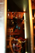
All caps connected as per original, wires from pcb to the pot removed. I took a picture of wireless and potless Rotel, so you don't think I skimped on that.🙂
C506 and C505 connected to E7 exactly as in your diagram.
Switch is noisy.
Attachments
Is it noisy in one or both channels like this ?
Keep the wire links in place and now short out R530 and R529
Noise present or not ?
Keep the wire links in place and now short out R530 and R529
Noise present or not ?
Is it noisy in one or both channels like this ?
Keep the wire links in place and now short out R530 and R529
Noise present or not ?
It is noisy just in the right channel as before.
By shorting out you mean jumper wire between R530 and R529?
Thanks
Marko
- Status
- Not open for further replies.
- Home
- Amplifiers
- Solid State
- Help with DC on volume pot