Questions are no problem...
The increased voltage across C518 and increased noise appears to be the case and in a way doesn't make sense.
I'll try and explain it better a little later 🙂
The gain of the transistors shouldn't have any effect. That is because the DC conditions and the AC gain is set entirely by the passive components. And with the transistors isolated I would say it really should be silent... and that it isn't is a real puzzle. This is where rigging a pot up to bias C518 comes in. We have to do that to see just what the effect is.
The actual value of C518 isn't very critical. It does two things,
1. It prevents and DC from passing from Q504 to the next stage. The value of the cap has no effect on that property apart from how long it takes to initially charge. Big cap = long time 🙂
2. The value of the capacitor determines how well it passes low frequencies in the audio. If it's not big enough then the bass will be cut off.
If we just placed a cap across R530 then the amp would be very quiet... and all the time. It would just "short out" all the audio signal to ground.
Mooly, thank you very much for your answers. 🙂
No problem... hopefully I'll come back with something later today. I want to try something because it's a puzzle is this one.
No problem... hopefully I'll come back with something later today. I want to try something because it's a puzzle is this one.
Please take as much time as needed, it is no rush. We already put a lot of time and effort into this so a day or two means nothing. I have T-amp for listening music while Rotel is on the workbench.
I did some more thinking 🙂 about that left channel that become silent, from the beginning of this topic we were focused on both channels and in one moment in time we established that the LEFT channel was silent and we let go of it.
If it is not transistor change that made it silent, what do you think about a theory that C517/C518 4.7 uf 25V change to 4.7uF 50V made it silent. We desoldered and changed C518 multiple times, what if I changed C517 to be the same type of cap as C518 and that was enough to stop popping in the LEFT but not in the RIGHT channel?
I wanted to take a good look at this as it's bugging me 🙂
The voltage rating of the caps won't make any difference to the noise, there is something we are missing with this.
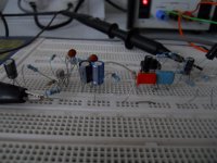
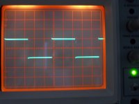
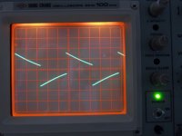
As we have just been going through all the theory with this I wanted to prove to myself that the circuit should behave as I keep saying and so I have gone and built the front end of the Rotel up on a breadboard. And it is silent when the low pass filter switch is operated. I coupled the output of the preamp to a high gain headphone amp and there was no noise or clicks as the switch operated. The two scope shots show the output with a 100hz squarewave and the filter in and out.
Just look back at post #188
We are absolutely sure that all there is correct. Yes 🙂 Everything rests on that being so.
I said before we could use a pot to bias C518 as a test. Thinking more about it, and I suspect it won't stable enough.
What I can't quite figure out is this...
The amp is silent until C518 is connected and we have eliminated C518 by both changing and swapping it.
If there were a problem with the first two transistor stage (Q502 and Q504) then that would have been "proved" when we cross coupled the stages feeding both channels.
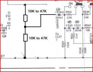
I think we have to bias C518 and see whether the noise is there. The pot won't be stable enough, any tiny change in voltage on the wiper will be audible. We need two resistors of either equal or not hugely dissimilar values and not to low in value. We connect them in series and across the preamp supply and connect the junction to C518 as shown.
The voltage rating of the caps won't make any difference to the noise, there is something we are missing with this.
As we have just been going through all the theory with this I wanted to prove to myself that the circuit should behave as I keep saying and so I have gone and built the front end of the Rotel up on a breadboard. And it is silent when the low pass filter switch is operated. I coupled the output of the preamp to a high gain headphone amp and there was no noise or clicks as the switch operated. The two scope shots show the output with a 100hz squarewave and the filter in and out.
Just look back at post #188
We are absolutely sure that all there is correct. Yes 🙂 Everything rests on that being so.
I said before we could use a pot to bias C518 as a test. Thinking more about it, and I suspect it won't stable enough.
What I can't quite figure out is this...
The amp is silent until C518 is connected and we have eliminated C518 by both changing and swapping it.
If there were a problem with the first two transistor stage (Q502 and Q504) then that would have been "proved" when we cross coupled the stages feeding both channels.
I think we have to bias C518 and see whether the noise is there. The pot won't be stable enough, any tiny change in voltage on the wiper will be audible. We need two resistors of either equal or not hugely dissimilar values and not to low in value. We connect them in series and across the preamp supply and connect the junction to C518 as shown.
Attachments

I wanted to take a good look at this as it's bugging me 🙂
The voltage rating of the caps won't make any difference to the noise, there is something we are missing with this.
As we have just been going through all the theory with this I wanted to prove to myself that the circuit should behave as I keep saying and so I have gone and built the front end of the Rotel up on a breadboard. And it is silent when the low pass filter switch is operated. I coupled the output of the preamp to a high gain headphone amp and there was no noise or clicks as the switch operated. The two scope shots show the output with a 100hz squarewave and the filter in and out.
Just look back at post #188
We are absolutely sure that all there is correct. Yes 🙂 Everything rests on that being so.
I said before we could use a pot to bias C518 as a test. Thinking more about it, and I suspect it won't stable enough.
What I can't quite figure out is this...
The amp is silent until C518 is connected and we have eliminated C518 by both changing and swapping it.
If there were a problem with the first two transistor stage (Q502 and Q504) then that would have been "proved" when we cross coupled the stages feeding both channels.
I think we have to bias C518 and see whether the noise is there. The pot won't be stable enough, any tiny change in voltage on the wiper will be audible. We need two resistors of either equal or not hugely dissimilar values and not to low in value. We connect them in series and across the preamp supply and connect the junction to C518 as shown.
WOW😛
Is everything I can say right now, to go trough all this trouble for some Borat from Croatia. I don't want to sound corny, but thank you just doesn't cut it for this. Please check your PM.
I looked at the post 188 and everything checks out there, we can rerun those test to be sure beyond 100%.😀
If I told you that yesterday I swapped C517/C518 4.7uF 50V Nichicon
with brand new Elna Silmic II 4.7uF 25V bought from a reputable place (hi-fi coll***) and that in that setup I get popping from both channels would you believe me?
If I told you that yesterday I swapped C517/C518 4.7uF 50V Nichicon
with brand new Elna Silmic II 4.7uF 25V bought from a reputable place (hi-fi coll***) and that in that setup I get popping from both channels would you believe me?
Yes I would believe you.
So with C517 (the "good" channel) swapped to use another cap, that channel now becomes noisy as well ? Is that what you mean ?
Yes I would believe you.
So with C517 (the "good" channel) swapped to use another cap, that channel now becomes noisy as well ? Is that what you mean ?
Yes, that is exactly what I mean, C517 changed to another cap is noisy as well while operating low filter switch.
And that cap is not the same type, brand or series that was in there before 4.7uF 50V was put in. The only thing in common with the first cap that was in is the value of 25V.
Interesting result in that it kind of proves that there must be a small DC leakage through these caps. If you have a cap that you are swapping and one is noisy and one not then it has to be so. I don't think there can be any other conclusion to that. What do you think ?
C527 and C528 are also very critical on this leakage issue too.
The circuit shows 25 volt caps as original. 50 volt or 25 volt... the leakage should be low.
Those caps are marked as "LN" types.
Something else... just to be sure 🙂 again 🙂 Are all these caps the correct values ? The circuit is a bit blurry. C506 is 1uF, C518 is 4.7uF and C528 is 1uF.
Just trying to cover every possibility. Maybe the original caps really did have a super low leakage more like Tantalums.
I'll try and measure some caps today for real and see if I can determine what the typical leakage is.
Interesting result in that it kind of proves that there must be a small DC leakage through these caps. If you have a cap that you are swapping and one is noisy and one not then it has to be so. I don't think there can be any other conclusion to that. What do you think ?
C527 and C528 are also very critical on this leakage issue too.
The circuit shows 25 volt caps as original. 50 volt or 25 volt... the leakage should be low.
Those caps are marked as "LN" types.
Something else... just to be sure 🙂 again 🙂 Are all these caps the correct values ? The circuit is a bit blurry. C506 is 1uF, C518 is 4.7uF and C528 is 1uF.
Just trying to cover every possibility. Maybe the original caps really did have a super low leakage more like Tantalums.
I'll try and measure some caps today for real and see if I can determine what the typical leakage is.
I agree with you, I just don't understand why the same type of cap (nichicon 50V) was good enough on one channel (LEFT) but not in the other, perhaps because of the higher voltage measured on collector of Q504 then that of Q503.
C506 and C518 are definitely of correct values, I have to check for C528. I took pictures before recapping and I wrote original value beside every cap that was taken out.
I ordered some 1uF Panasonic polyester caps and they are on their way. I am trying to source something in 4.7uF with 5mm lead space but that is proving to be rather difficult.
Is it possible that in 1979. such super low leakage caps even existed, I thought technology of caps improved over the years.
Another little test as it's good to go over theory and practice once in a while.
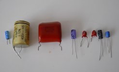
Yes, modern caps are pretty good. You can see here how all the electrolytics are actually quite leaky. Look also how the two similar Tantalums vary so much. The Panasonic and Dubilier were the best of the electroylitics here.
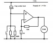
So to see just how leaky are caps, old, modern and of different types are I rigged up a TLO71 opamp as a DC amplifier as shown. By dividing the voltages at the opamp output by 11 we get the DC voltage across the resistor Rbias. Ohms law would give us the current. It's more of a graphic example showing the voltages though. The voltage across Rbias should be zero of course for a theoretically perfect cap.
Each cap was tested as follows. The test began with Rbias shorted for a few seconds to bring the cap up to charge. The short was removed leaving the 100K and 6.8M resistors in place. The reading was taken and I called that the 100K reading. The 100K was then removed leaving just the 6.8M and I waited 1 minute for the reading to stabilise (which it didn't always). That is the 6.8M reading.
Capacitor, Rbias and the actual Rbias Voltage
1. 2.2uF/16v ancient electroylitic. 6.8M 62mv
100K 1.36mv
2. 2.2uF/400v Mixed Dielectric. 6.8M 1.1mv
100K 0.1mv
3. 4.7uF/100v Film 6.8M 2.2mv
100K 0.136mv
4. 10uF/100v Dubilier Electroylitic 6.8M 0.11v
100K 3.2mv
5. 22uF/16v Tantalum (Tant 1) 6.8M 6.8mv
100K 0.36mv
6. 22uF/16v Tantalum (Tant 2) 6.8M 72mv
100K 3.6mv
7. 22uF/16v (Multicomp brand) 6.8M 0.33v (still climbing)
100K 18mv
8. 47uF/16V Panasonic Audio series cap 6.8M 0.145v (still climbing)
100K 12mv
Yes, modern caps are pretty good. You can see here how all the electrolytics are actually quite leaky. Look also how the two similar Tantalums vary so much. The Panasonic and Dubilier were the best of the electroylitics here.
So to see just how leaky are caps, old, modern and of different types are I rigged up a TLO71 opamp as a DC amplifier as shown. By dividing the voltages at the opamp output by 11 we get the DC voltage across the resistor Rbias. Ohms law would give us the current. It's more of a graphic example showing the voltages though. The voltage across Rbias should be zero of course for a theoretically perfect cap.
Each cap was tested as follows. The test began with Rbias shorted for a few seconds to bring the cap up to charge. The short was removed leaving the 100K and 6.8M resistors in place. The reading was taken and I called that the 100K reading. The 100K was then removed leaving just the 6.8M and I waited 1 minute for the reading to stabilise (which it didn't always). That is the 6.8M reading.
Capacitor, Rbias and the actual Rbias Voltage
1. 2.2uF/16v ancient electroylitic. 6.8M 62mv
100K 1.36mv
2. 2.2uF/400v Mixed Dielectric. 6.8M 1.1mv
100K 0.1mv
3. 4.7uF/100v Film 6.8M 2.2mv
100K 0.136mv
4. 10uF/100v Dubilier Electroylitic 6.8M 0.11v
100K 3.2mv
5. 22uF/16v Tantalum (Tant 1) 6.8M 6.8mv
100K 0.36mv
6. 22uF/16v Tantalum (Tant 2) 6.8M 72mv
100K 3.6mv
7. 22uF/16v (Multicomp brand) 6.8M 0.33v (still climbing)
100K 18mv
8. 47uF/16V Panasonic Audio series cap 6.8M 0.145v (still climbing)
100K 12mv
Attachments
That doesn't read very well 😉
Yes, modern caps are pretty good. You can see here how all the electrolytics are actually quite leaky
Modern caps are better for reliability and ripple current ratings, temperature ratings and so on, but all the standard types I have are all quite leaky in practice.
I haven't got any specifically marked "low leakage" electroylitics.
Interesting......
I find that when freshly reformed that a good leakage value usually results.
I don't know how long that good result holds for. Is it days or weeks or months?
But, for this testing when you are working with minutes and hours, a very slowly reformed electrolytic can get down to extremely low leakage.
I don't know how long that good result holds for. Is it days or weeks or months?
But, for this testing when you are working with minutes and hours, a very slowly reformed electrolytic can get down to extremely low leakage.
I find that when freshly reformed that a good leakage value usually results.
I don't know how long that good result holds for. Is it days or weeks or months?
But, for this testing when you are working with minutes and hours, a very slowly reformed electrolytic can get down to extremely low leakage.
Well I actually thought about this part way through testing and I tried it on just one, the Panasonic 16 volt cap. I took it up to 16 volts for a minute or so and then tested again. The leakage was definitely a little lower (around 30% or so) but seemed to creep back up again.
Maybe if caps that are held (formed) at their working voltage for a lot longer, then the effect may be better.
That doesn't read very well 😉
Yes, modern caps are pretty good. You can see here how all the electrolytics are actually quite leaky
Modern caps are better for reliability and ripple current ratings, temperature ratings and so on, but all the standard types I have are all quite leaky in practice.
I haven't got any specifically marked "low leakage" electroylitics.
Interesting......
I find your measurements Mooly very interesting.
Is there any good side to electrolytics then, except for capacitance and size, in audio purpose?
If you could be so kind to PM me your address I would like to donate some some ELNA RLB low leakage caps for scientific purposes and f you are willing to prove legality of 2SC2240 I bought I would also like to send you some?
@AndrewT
If I understood you correctly, I should perhaps give some forming time to those freshly installed ELNAs 4.7uF 25V caps.
Normally electroylitics are fine in audio if used correctly.
The big problem (the way it's designed) with the Rotel is that the preamp feeds directly into the power amp. Normally the volume control is between the two and so at any normal setting any noise/s from the preamp (not just from switches but normal circuit hiss too) is attenuated by the volume setting. The Rotel runs "flat out" all the time with the volume control attenuating just the input signal.
Does that make sense ? It is a big design issue really. It means the slightest disturbance to the steady state conditions in the amp could be audible.
It's very difficult sometimes to spot fake transistors if the markings are good. It's not just gain that can be low or out of spec... if it's fake then it's a different device altogether and all the properties are different. Too measure all that is a complex procedure involving a lot of specialised equipment... measuring junction capacitance, transition frequencies etc which are in the tens and hundreds of Mhz region.
Lets see how you get on with some different caps fitted. The 1uF Panasonic films will at least work in the C518 and C528 positions. The only downside would be lack of bass at very low frequencies but it will prove the cap question.
slow reforming is not minutes.Well I actually thought about this part way through testing and I tried it on just one, the Panasonic 16 volt cap. I took it up to 16 volts for a minute or so and then tested again. The leakage was definitely a little lower (around 30% or so) but seemed to creep back up again.
Maybe if caps that are held (formed) at their working voltage for a lot longer, then the effect may be better.
1M0 with a voltage of ~63Volts will give a starting current of 63uA and dropping as the hours pass.
Then when the cap is ~75% charged I will change to a 100k, again to get uA into the cap.
Then leave it soaking at this charging voltage for at least 24hrs after it has apparently been reformed and it gets better throughout this longwinded process. A big cap can take 3days.
I can believe the leakage comes down significantly over a very long period of time although it's not something I have ever tried and measured results for. I don't know how long it would last either.
Unless I'm imagining it, I seem to remember somewhere mkusan mentioning that the noise diminished as the amp was left powered... which again points to cap leakage reducing.
I think trying the 1uF films has to be the easy way to prove this.
Unless I'm imagining it, I seem to remember somewhere mkusan mentioning that the noise diminished as the amp was left powered... which again points to cap leakage reducing.
I think trying the 1uF films has to be the easy way to prove this.
Normally electroylitics are fine in audio if used correctly.
The big problem (the way it's designed) with the Rotel is that the preamp feeds directly into the power amp. Normally the volume control is between the two and so at any normal setting any noise/s from the preamp (not just from switches but normal circuit hiss too) is attenuated by the volume setting. The Rotel runs "flat out" all the time with the volume control attenuating just the input signal.
Does that make sense ? It is a big design issue really. It means the slightest disturbance to the steady state conditions in the amp could be audible.
It's very difficult sometimes to spot fake transistors if the markings are good. It's not just gain that can be low or out of spec... if it's fake then it's a different device altogether and all the properties are different. Too measure all that is a complex procedure involving a lot of specialised equipment... measuring junction capacitance, transition frequencies etc which are in the tens and hundreds of Mhz region.
Lets see how you get on with some different caps fitted. The 1uF Panasonic films will at least work in the C518 and C528 positions. The only downside would be lack of bass at very low frequencies but it will prove the cap question.
Can we make analogy between Rotel and a car who has gas pedal welded to the metal, always driving maximum speed and in order to drive more slowly it has to apply the brakes?
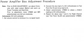
If I got it right, what I don't understand is why is then the heat sink of the output transistors mildly hot in standby or on low listening levels, and hotter on higher listening levels. Wouldn't it then be equally warm always, see the picture for bias adjustment. Do you have any idea why Rotel engineers choose such design, any benefits to it?
I left the amplifier on overnight, you are right about my remarks about noise getting softer with warm up time, now is also such a case, noise was there in the morning, slightly softer but still there. That was the primary reason for transistor change, I suspected thermally unstable component. Idea of a cap leakage seizing with charging never even crossed my mind.
I will tonight exchange C516 to low leakage 1uf ELNA, C528 already is that cap. I have a question🙂, I left amp in post #217 state (Q504,Q502,C516,C510 removed), should I revert those changes?
I must admit I have a fear of the results, I am not entirely convinced about C517 and C518 leaking being the only root of the noise, although everything points to it. All this time I was hoping for a double meal🙂, something that would explain the popping of low filter switch and the scratchinesses of the pot? Can you see that happen, new TKD not being faulty?
Attachments
Can we make analogy between Rotel and a car who has gas pedal welded to the metal, always driving maximum speed and in order to drive more slowly it has to apply the brakes?
If I got it right, what I don't understand is why is then the heat sink of the output transistors mildly hot in standby or on low listening levels, and hotter on higher listening levels. Wouldn't it then be equally warm always, see the picture for bias adjustment. Do you have any idea why Rotel engineers choose such design, any benefits to it?
It's a little bit like the car but not quite 🙂... very hard to explain.
On any amplifier the bias current is independant of the gain of the amplifier.
The temperature will only rise as the amp drives current into the speakers.
If you removed C545 and C546 to isolate the power amp it would still get just as hot when sat powered up and silent.
Do you see 🙂
I will tonight exchange C516 to low leakage 1uf ELNA, C528 already is that cap. I have a question🙂, I left amp in post #217 state (Q504,Q502,C516,C510 removed), should I revert those changes?
I must admit I have a fear of the results, I am not entirely convinced about C517 and C518 leaking being the only root of the noise, although everything points to it. All this time I was hoping for a double meal🙂, something that would explain the popping of low filter switch and the scratchinesses of the pot? Can you see that happen, new TKD not being faulty?
I must admit I have a fear of the results you're not the only one 😉
You mention that changing C517 for another cap made that (the good) channel noisy too.
Yes, you can leave those parts isolated to test initially.
I might have a little fun test that you can do on some caps with your DVM. I'll try it first though.
Changing C517 to another cap made left, good until then, channel noisy, no doubt about it.
Do you want me to exchange C517 to low leakage type also?
- Status
- Not open for further replies.
- Home
- Amplifiers
- Solid State
- Help with DC on volume pot