I don't want to pollute Jeff's thread, so if this is going to provoke a long discussion I'll start a thread for it.
I am following this thread as I am am relative newbie trying to devise a screen regulator for the output stage of and 807/6L6 style PP output stage for up to 50W or so.
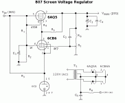
Been there; done that. I designed a project using Class AB1 807s, and this hollow state voltage regulator. I went hollow state for this because I didn't have any suitable high voltage transistors, and I had never done this before with VTs instead of transistors. I also worked up an alternative design as well. Though it's nothing fancy, it held its output within 0.8Vdc as the rail varied by 40Vdc.
Attachments
Found a nice design I want to alter....
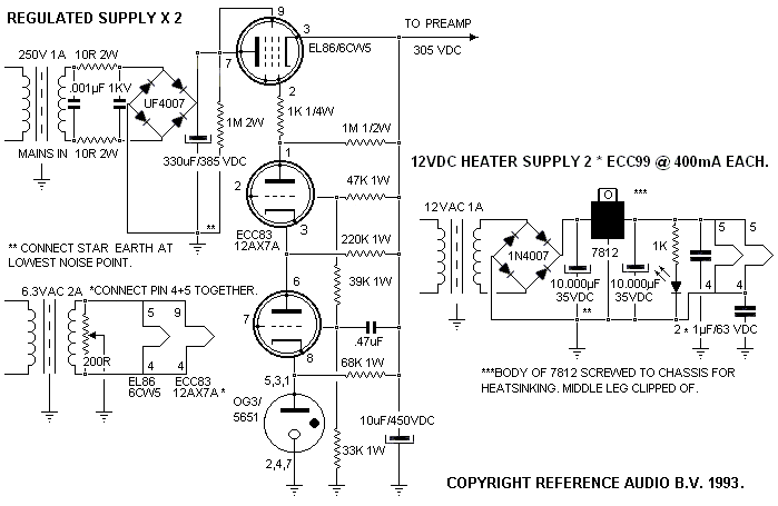
I found this design on the forum on the "Frank's ultimate preamp" thread. I like it very much b/c I have most of the parts and the design is pretty simple. One proble though is this was designed to produce a set output without ability to adjust to final B+. I think it can be slightly modified by the addition of a 100K pot in place of the 47K resistor on the input to the grid of the first 12ax7 section. I am not real certain of this and wanted some advice here. Would this in fact give this circuit the needed adjustment capabilities or should the variable resistance be placed elsewhere.
Here is the schematic:

Again, I plan to add some LC filtering before the regulator.
Jeff
I found this design on the forum on the "Frank's ultimate preamp" thread. I like it very much b/c I have most of the parts and the design is pretty simple. One proble though is this was designed to produce a set output without ability to adjust to final B+. I think it can be slightly modified by the addition of a 100K pot in place of the 47K resistor on the input to the grid of the first 12ax7 section. I am not real certain of this and wanted some advice here. Would this in fact give this circuit the needed adjustment capabilities or should the variable resistance be placed elsewhere.
Here is the schematic:

Again, I plan to add some LC filtering before the regulator.
Jeff
I would replace the 47k and 39k resistors with, say, 33k and 27k respectively and add a potentiometer between them, say 25k, with the wiper going to the 12AX7 grid. That should give you nice control over the regulated voltage.
I am not sure why the second triode is there, except perhaps to reduce the potential on the first one. Seems unnecessary to me.
In addition, the 1M resistor in the screen of the pass tube is incorrect unless I misread the diagram. The screen either needs a resistor to the plate or direct connection to it. Maybe the connection dot is missing.
<snip>
I am not sure why the second triode is there, except perhaps to reduce the potential on the first one. Seems unnecessary to me.
In addition, the 1M resistor in the screen of the pass tube is incorrect unless I misread the diagram. The screen either needs a resistor to the plate or direct connection to it. Maybe the connection dot is missing.
It's a cascode, provides some additional gain and the ability to operate at higher voltages.
The 1M resistor is a bleeder and the dot connecting plate and screen that you cannot see is clearly visible in the linux version of Firefox.
It is not a well drawn schematic.
Last edited:
So maybe I should switch to Linux.
Yeah I recognized the cascode but don't think it's justified, unless as we both said, someone wanted higher voltage. I believe the 5651 is 87 Volts so the grid of that tube should be a bit lower than that.
Also one should bear in mind the limitation of heater-cathode voltage on the tube.
Yeah I recognized the cascode but don't think it's justified, unless as we both said, someone wanted higher voltage. I believe the 5651 is 87 Volts so the grid of that tube should be a bit lower than that.
Also one should bear in mind the limitation of heater-cathode voltage on the tube.
So maybe I should switch to Linux.
Yeah I recognized the cascode but don't think it's justified, unless as we both said, someone wanted higher voltage. I believe the 5651 is 87 Volts so the grid of that tube should be a bit lower than that.
Also one should bear in mind the limitation of heater-cathode voltage on the tube.
I recommend Linux (particularly Ubuntu) just about any opportunity I get.. 😀
The latest version of Wine will run an impressive number of Windows apps without many issues. It does require a bit of tinkering if you want to do the sorts of things I do with it, but for me that is part of the fun. (Others may not agree..) 😀
I use cascodes extensively in my own designs and find the additional 15 - 20dB of gain useful in many instances. Where it doesn't work so well is in applications where less than 200V is required unless you use something like the 6DJ8 as an error amplifier.
As far as the filament to cathode insulation rating is concerned I use a dedicated filament winding and typically run it at the mid point value between the cathodes - this seems to work fine as long as you don't exceed the rating. Single triodes of course would not have this limitation. (with separate dedicated filament windings)
I also use pentode (tetrode) connected pass tubes as they make better followers in many instances and provided a well filtered screen supply is used can greatly improve ripple rejection.
I often use 5651 or 85A2 (0G3) as references and find they work well, their high dynamic impedance does result in unintended cathode degeneration, however they seem to drift less than zeners in my experience.
- Status
- Not open for further replies.
- Home
- Amplifiers
- Tubes / Valves
- Help with creating a simple tube HV regulated supply
