I was wondering if anybody had a fairly simple schematic to design a tube regulated HV supply for 300v for a preamp I want to build. Is it Kosher to put a tube regulator after a CLC filter? I want almost no ripple when it is all said and done. This will obviously be my first attempt a a regulated HV supply, I have always wanted to try one but really don't have the first clue of where to start. I have seen several schematics out there but none creating 300v so I haven't been able to just copy one to date. I want to keep this as simple as possible.
Thanks for your help in advance, you guys always come through here!
Jeff
Thanks for your help in advance, you guys always come through here!
Jeff
Jeff,
I have an HP650A sine wave generator that has a simple tube regulated supply. You should be able to find a schematic easily on the internet. It is adjustable through a resistor divider.
Heath
I have an HP650A sine wave generator that has a simple tube regulated supply. You should be able to find a schematic easily on the internet. It is adjustable through a resistor divider.
Heath
Does the regulator have to be tube? Maida style regulator can be made with LM317 voltage regulator. If tube is requirement, found this with a google search, might be useful - Regulated HV power supply
This was scanned from an issue of Sound Practices. The tube is a 6BM8 although you could probably sub in something similar without too many problems.
Attachments
Last edited:
Make life easy and use VR tubes. You need 300 Volts? Use a pair of 0A2 in series, or a pair of VR150s. As long as you have enough striking voltage available, this makes for an extremely simple yet effective regulator.
Make life easy and use VR tubes. You need 300 Volts? Use a pair of 0A2 in series, or a pair of VR150s. As long as you have enough striking voltage available, this makes for an extremely simple yet effective regulator.
Good reference for VR circuits. Basic VR Tube Regulator Circuit
Make life easy and use VR tubes. You need 300 Volts? Use a pair of 0A2 in series, or a pair of VR150s. As long as you have enough striking voltage available, this makes for an extremely simple yet effective regulator.
How much striking voltage is required for a Vmax of 300-325V?
Jeff
Here is the one i used
Hi.
I have used this design successfully for 3 of my preamps. Yes I use a clc filter prior to it and its good for 100mA. It is not my design and the schematic is annotated to its rightful designer.
Hope it works for you.
ps this design was available on a chinese based web site so I assume that its cool to post it. My apologies if it isnt. It was a list of mods to the lsdy regulated voltage kit addressing a few of it shortcomings.
Attachments
Last edited:
Make life easy and use VR tubes. You need 300 Volts? Use a pair of 0A2 in series, or a pair of VR150s. As long as you have enough striking voltage available, this makes for an extremely simple yet effective regulator.
OK, I did a little research on the OD3 and OA2 VR150 type tubes. I never knew much about these things until now. Very interesting device, the NEETS module does a pretty good job of explaining how they work.
A couple of questions though, you say to use 2 of these in series....so would my final B+ come from the cathode of the 2nd tube in series?
The NJ7P database shows the Vmax supply voltage to be 185v for both of these tubes. To get the 300V I need the first tube in series would see 300v thus exceeding the specs. I am not sure how this works really though. Wouldn't the first VR tube in the series limit the voltage to 150 seen at the plate of the second tube??? How can 2 of these tubes in series provide the 300V in the end if they are designed to regulate the voltage to 150. Seems to me the finel voltage of two of these in series would be 150V, just "double regulated" now. I don't understand.....please enlighten me. It is not that I don't believe you, I just don't see how this works.
Jeff
Edit:
I just went back and reviewed the NEETs module on VR circuits and not just the VR tube itself. I think I understand now, the series of VR150 tubes is placed across the B+ and ground, in parallel to the load. Thus the VR series of tubes acts like a shunt. My final B+ should be taken from the top (plate) of the first tube in series.....am I correct in this now?
Thanks,
Jeff
Last edited:
Think of the VR tubes as shunt regulators, kind of how you would employ zener diodes. You totem pole the VR tubes; top end connected to the voltage you are trying to regulate, the bottom to ground. If the supply voltage is too high, then you need to put dropping resistors in series before the voltage supply gets to the VR tubes. Resistance values have to be calculated by what your load current is.
VR tubes can not have much current going through them or you will fry them. If you end up making a simple VR tube only regulator, you have to calculate the current pull of your circuit plus the current that is permissable through the VR tube to find out what series resistance value you need to use in the supply rail.
How many milliamps does your circuit pull? If it's more than maybe 10ma (I'm guessing here; look at the VR tube specs) then consider using a pass tube connected to an error amp (which is connected to the VR tube through its grid).
One more thing Vr tubes like A LITTLE capacitor across them which helps with regulation. Something like .05uf, if I recall.
Hope this answers your questions... Daniel
If you don't mind a little sand in your glass, the good ol' National LM317 High Voltage Regulator would work. If you need higher output current, just lower R3. The voltage across R3 should not exceed about 2.5 V at the max output current.
~Tom
~Tom
Take a look at this thread: http://www.diyaudio.com/forums/tubes-valves/153607-tube-voltage-regulator-worth-effort.html
Post 22 references one of my designs, but there is a lot of good material throughout the thread if you are interested in using a tube based regulator. The regulator mentioned in my post was designed specifically for audio applications and works quite well.
Sqerus incidentally developed a very good design of his own during the course of this thread..
My circuit should pull no more than about 5-8mA. It is a simple 12AX7 triode voltage amplifier followed by a 12AX7 cathode follower. I am figuring about 1mA at idle for the voltage stage and about 1.5mA for the cathode follower. That is 2.5mA a side, for stereo 5mA on the total circuit while at idle. Peak voltage should be no more than 8mA. So basically if I put a CLC filter in the first part of my PSU then a voltage dropping resistor to get the voltage down to 300 at a estimated 8mA current then I could place the VR150's across the B+ and ground? This would allow the difference of the 3mA from peak to idle to be regulated by the VR150'S I guess. It makes sense to me. These tubes are pretty cheap too at Tube Depot, about $6 each.
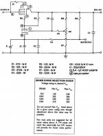
What is a good source for buying the 5W 100v zeneer diode? Kevinkr, I like your schematic referenced in post 22 of the article you mentioned. I have all the parts except the zeneer. Kevin, so you are saying, if I am correct, I should provide a voltage of about 400v on the raw B+ before the regulator for a well regulated 300V output (with the circuit you referenced)?
What should be my target ripple on the raw B+ prior to the regulator? I was thinking of using a 6X4 rectifier and a CLC filter before the regulator circuit, any problems you see with this? As mentioned earlier, my whole circuit should not ever consume more than 10mA, I think.
Thanks for your help,
Jeff
What is a good source for buying the 5W 100v zeneer diode? Kevinkr, I like your schematic referenced in post 22 of the article you mentioned. I have all the parts except the zeneer. Kevin, so you are saying, if I am correct, I should provide a voltage of about 400v on the raw B+ before the regulator for a well regulated 300V output (with the circuit you referenced)?
What should be my target ripple on the raw B+ prior to the regulator? I was thinking of using a 6X4 rectifier and a CLC filter before the regulator circuit, any problems you see with this? As mentioned earlier, my whole circuit should not ever consume more than 10mA, I think.
Thanks for your help,
Jeff
Hi Jeff,
Check with Mouser or Digikey - they should have 100V 5% 5W zeners. Note that is fine to use a 1W zener in this application, and if you decide to use a 5W zener it may be a good idea to increase the zener current - try it and if drift is excessive change R2 and R3 to 33K 1W resistors, and C2 to 3.3uF. What you propose should work just fine for the required current, however you can build it as shown without an additional filter ahead of the regulator and ripple should be <1mVrms at the output. IMO The CLC is worthwhile and should give you ridiculously low ripple at the output.
If you want to build right now you can just series up a bunch of lower voltage zeners to get the reference voltage you need.
Note that 400V is the minimum, and values above that will slightly enhance performance, anywhere between 400V and 500V at your load current is fine. Just make sure caps are rated for the supply voltage...
FWIW my system has a lot of these or variations of these regulators in it.. 😀
Last edited:
VR tubes as screen reg?
I don't want to pollute Jeff's thread, so if this is going to provoke a long discussion I'll start a thread for it.
I am following this thread as I am am relative newbie trying to devise a screen regulator for the output stage of and 807/6L6 style PP output stage for up to 50W or so. The actual tubes will be 5B254M (Locktal 807 with plate cap) with B+ somewhere in the 400-500v area (depends on the PT I finally use). With these tubes the screen max is 300v.
As I see it from the data sheet for the 5B254M, the screen current will vary from zip to about 16mA per pair of tubes in AB2 at 75W.
I have looked at altering Pete Millett's red board 150v reg for 300v, and that is probably the simplest SS reg for the job but means some heatsinking (although I will probably be using MOSFET grid drive, so I may be able to share that heatsink if the PS is on the same chassis as the amp).
I have looked at individual LR8N3 regs for each tube, but the high B+ and SS rectification means a lot of precautions are needed to protect it at switch on (when the B+ will hit 600v). B+ will have to be on a delay anyway I think.
However, I do have a couple of 150B2 VR tubes. Would they be suitable? The load current is going over their max of 15mA at max signal so it's probably a long shot.
Thanks in advance, and apologies to Jeff if this intrudes on his design.
Gary
I don't want to pollute Jeff's thread, so if this is going to provoke a long discussion I'll start a thread for it.
I am following this thread as I am am relative newbie trying to devise a screen regulator for the output stage of and 807/6L6 style PP output stage for up to 50W or so. The actual tubes will be 5B254M (Locktal 807 with plate cap) with B+ somewhere in the 400-500v area (depends on the PT I finally use). With these tubes the screen max is 300v.
As I see it from the data sheet for the 5B254M, the screen current will vary from zip to about 16mA per pair of tubes in AB2 at 75W.
<snip>
Thanks in advance, and apologies to Jeff if this intrudes on his design.
Gary
Take a look here for a potential option, note that you could replace the pass tube referenced with 5B254M if you wanted: http://www.diyaudio.com/forums/tubes-valves/90020-perfect-tube-regulator.html Note that the name of the thread has nothing to do with me, 😀, I posted the design as a potential answer to the design question at hand.. (Note that nothing in life is perfect, but it is probably good enough - a number of friends use this design as a screen reference supply in pentode amps like yours.)
Last edited:
What is a good source for buying the 5W 100v zeneer diode?......Check with Mouser or Digikey
It just happens that I have been working on a similar project. I have wired two Simple P-P boards together to make a killer 50 WPC stereo amp. I am running the plates of the EL84's right off of a tube rectified Antek 4T360 toroid at 425 volts. The screens need to be regulated and adjustable from 300 to 340 volts. For visual effect I want to use VR tubes but physical limitations force 9 pin tubes. The back up plan is zener diodes. I ordered the parts last week from Mouser. They are out of stock on 100V 5W diodes, so I got 1W parts. The part number is 1N4764A-TAP.
The current demand (measured on the working amp) for 8 EL84 screens and 4 12AT7's ranges from 55 ma to 120 ma depending on how hard you bang on the amp. This rules out a simple resistor and VR tube circuit. I will probably use a simple follower type pass circuit since it is sufficient for this application. Tubes are the preferred pass device. A 6AV5 maybe.
George, With all of the "experiments" will you have any Simple PP boards left to sell?
A while back I read an article on Broskie's TubeCad Journal on a tube based shunt regulator. It was very simple and a good read. I'll see if I can post a link. IIRC it isn't too much different than the above, except I don't recal such a large zener.
A while back I read an article on Broskie's TubeCad Journal on a tube based shunt regulator. It was very simple and a good read. I'll see if I can post a link. IIRC it isn't too much different than the above, except I don't recal such a large zener.
Last edited:
George, With all of the "experiments" will you have any Simple PP boards left to sell?
Yeah, I bought 110 of them and have sold 11, given away 2, and built 5 myself. Board sales in general have dwindled to 2 or 3 a week, so I have enough of all 3 to last out the year at least.
A while back I read an article on Broskie's TubeCad Journal on a tube based shunt regulator.
There have been threads related to tube and SS shunt regulators on this forum. There is a discussion surfacing in SY's RLD amp thread about a No Light District design (or several) where the LED's are essentially replaced by SS shunt regulators. A link to a shunt regulator wiki is posted there. A few SS shunt regulator circuits have been proposed. I have breadboarded a simple shunt regulator circuit using an LM431 chip. A pair of these were built and tested in the cathode circuit of one channel of the Simple P-P, while the screens and the rest of the amp were running on a regulated bench supply (hence the need for the simple series regulator design). The performance was outstanding (50 watts at 0.7% distortion and over 60 watts at clip).
I ordered parts to make 8 of these circuits, test some really simple things like just stuffing some big zeners in the cathodes, and breadboard the screen regulator, but two of lifes interruptions have put my tube time back on hold for at least a month.
My 11 year old station wagon has finally died (it has been warning me for about a year), so we spent the entire weekend car shopping. My mother in laws health has taken a turn for the worse, so we have decided to move up our planned visit to soon. As soon as I can finish up test circuit design, and do a 10 layer PC board layout for it at work. If plans go right I will stop at the Dayton hamfest on the way back, so I won't see any Tubelab time until late May.
- Status
- Not open for further replies.
- Home
- Amplifiers
- Tubes / Valves
- Help with creating a simple tube HV regulated supply