
Excellent, and I'm using 100 ohms in mine 🙂 No ringing now you don't need a clamp on it but it may still help.. did you get a load on it yet?
Chris,
No load yet, I am still blowing the power supply fuses. Anymore ideas short of getting new torroidal core material?
No load yet, I am still blowing the power supply fuses. Anymore ideas short of getting new torroidal core material?
well that's where it would be worth trying it with a load and if you're red core has proven to be unsuitable... it's defenitly a critical component to have right.
Is all that's blowing at this point your fuses? Current protection can be a consideration as well. Maybe you just need bigger fuses too, do they sag when it's running at idle or heat?
Is all that's blowing at this point your fuses? Current protection can be a consideration as well. Maybe you just need bigger fuses too, do they sag when it's running at idle or heat?
Chris,
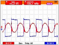
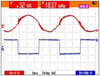
I just placed a 30 ohm load on the output of the amplifier and my problems dissapear... It amplifies the 100hz signal just like it should... I am happy, but not really because I don't want an amplifier that blows itself up when a speaker is disconnected. Any ideas as to what the problem might be and how I can fix this ?
Thanks!
-=Randy
I think you'd have to look at the feedback network for that. That's more where a zobel can be used if the q of your filter is peaking without a load but ideally you wouldnt' need it.
That's more phase accurate's area than my own, not to volunteer him, you could jump on the simulator yourself and see what you come up with, let us know.
Hi,
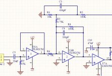
the simplest tweak you might try is active damping of output filter resonance. You can achieve that by placing capacitor between output (post filter) and pin 6 (- input of integrator U6B). I would start with something like 22pF to be on the safe side, although I guess actual size might be somewhere 47pF to 100pF.
For explanation of active damping look at Carver Patent US5,606,289 .
Best regards,
Jaka Racman
IMHO, what you have done by increasing the gate resistor is slowing down the switching speed, so dV/dt is smaller and resonance in the coil is not triggered (or is triggered to a smaller extent). I think it is not a question of dead-time per-se.
The problem is that, with a very high resistor in the gate, you will get higher THD due to dead-time depending on the final switching rise/fall times. However, it depends on what mosfets are you using.
Can you also accurately measure rise/fall time (you will need at least a 100MHz oscilloscope for that)
Pierre
"Triggering" is the right keyword IMO. There are some parasitic resonances that are "struck" by the switching transient.
Try to lower these and/or add some snubbers. Then decrease the gate resistors again.
Maybe your electrolytics in the PSU lines are "too good", i.e. they have to low an ESR.
Regards
Charles
Try to lower these and/or add some snubbers. Then decrease the gate resistors again.
Maybe your electrolytics in the PSU lines are "too good", i.e. they have to low an ESR.
Regards
Charles
I would also try snubbers first.
The first approach is to add a R in series with a C, from the switching output to GND. Use non-inductive resistor and high-voltage high frequency capacitor.
Try, for example, 1nF/250V + 10 ohm/2W...
But first, I would listen to a FM radio near the amplifier, to see if there is any audible interference. This way you will be much happier when you remove it with the snubber ;-)
... and tell us how it goes.
Hi,
Jaka, great tip🙂
Pierre, I agree that dv/dt would be slightly reduced, but the mosfet is still going to switch lightning fast, we're talking about a few extra nano seconds I'm guessing.
I have a hard time allowing myself to believe that could mean the difference from triggering this parasitic tank into oscillation or not?
Don't dismiss what a bit of "soft" dead time can do... look how slow the body diode of this mosfet recovers, ~250ns typical to 500ns max, "typically" that's five times longer than in a decent device. It's not by any means the worst of devices, and far from the best. Can it do the job though? Probably just, at 100Khz...
I think the temp of the device is an important tool at this stage of the game. It could indicate weither or not the overshoot was caused by parasitic resonance or shoot through. You might think that with a 33 ohm gate resistor it's got to run hotter because of the increased transition time, and it will, unless it significantly reduces shoot through via the saturated body diode.
I too am of course in agreement, while the bigger resistor "works" it's not optimal. What it is is simply a starting point in that it helps confirm the suspicions of what's going on with it.
Where to take it from here? I think we all gave some great advice on that. Personally though, I'd be looking for that better mosfet first, the one where the rise/fall/delay times just "work" .. faster recovery body diode.. etc. That'll lesson the requirement for deadtime as well as a slower dv/dt.
Short of redesigning the PCB one little tip to minimize strays I'll share with you is to make sure your mosfet leads are as short as possible, every little bit helps, once again device selection will play the biggest roll here. Also don't leave a long lead from the switching node to your inductor.
Once you've got the most well behaved mosfet you can find and your deadtime is OK, then you can consider adding snubbers if still required to qwell any ringing. It's entirely pointless to mess with snubbers before you've taken those steps.
Even if you're using the same model device as Pete used, it may be from a different manufacturer, from a different process, and the parasitics may not coincide with each other at all. So the right mosfet will make or break this, and the right mosfet is the one that works best, so that means trying out a few different ones that you think might work ok.
There's also no substitute for a little bit of research and hard work, which you'll have to do to find a good mosfet, or design snubbers.... or...
Regards,
Chris
I agree completely.
The first thing to do is to select the mosfets properly.
Have a look at a thread I started "Mosfet reliability in Class-D amplifiers". It is very educational.
Best regards.
The first thing to do is to select the mosfets properly.
Have a look at a thread I started "Mosfet reliability in Class-D amplifiers". It is very educational.
Best regards.
Hello!
I appreciate all the great advice!
I like the active damping idea and I will give this circuit a try as soon as I'm finished moving, but if I were to switch to say "Charles PID feedback" or "Bruno's UcD method" [assuming I have enough phase margin etc.] would those post-filter feedback topologies have the added advantage of active damping or do my filter resonance problem need to be addressed seperately?
I spoke with Peter and he did not have any resonance problems with his amplifier and this bothers me... Could the wrong type of dielectric material be causing problems? The capacitor I used is a 0.47uF, 250 V orange colored one I had lying around in my parts bin. It is rectangular in shape and the pin spacing is about 1" I am guessing it is a polypropylene... Is this the incorrect type of capacitor to use for an output filter? The cap does not heat up or do anything strange...
_____________________________________________________
It sounds like the voltage spikes are most likely caused by the MOSFETS or PCB parasitics. I have access to an environmental chamber. If I observed the voltage spikes with a scope and swept the temp from 10degC to 90degC it should get progressively worse as temperature increases, correct? [assuming the MOSFET was the source of my problem]
I am currently using an IRF644N NOT an IRF640N:
http://www.irf.com/product-info/datasheets/data/irf644n.pdf
Package = TO-220
VDss = 250V
RDS(on) = 240milli ohms
Id = 14 Amps
Single Pulse Avalnanche Energy = 180mJ
Avalanche Current = 8.4A
Repetitive Avalanche Energy = 15mJ
dv/dt = 7.9V/nS
Qg = 54nC
Qmiller = 26nC
I will read through the "MOSFET RELIABILITY..." thread.
Anyway, it sounds like I have a lot more testing to do! I LOVE IT!
Thanks!
-=Randy
I'm in the process of ordering more parts, anyway, subwo1, classd4sure and johnw said they all were impressed with the performance of an amidon type 2 red torroidal core.
According to: ttp://www.amidoncorp.com/aai_cost_ironpowderapplication.htm "type 2" material looks to be iron powder...
1. Could using ferrite instead of iron powder cause my filter to go crazy?
2. Doesn't ferrite have a more linear B-H curve vs iron powder?
3. What type of core is that hypex and lcaudio are using? Pot Core / ferrite?
Thanks!
-=Randy
Great to see you're having a great time.🙂 Here are a couple of thoughts which came to my mind which pertain to some aspects of your questions. They may need to be revisited by other members.
The feedback after the filter is able to damp filter resonance so long as the amplifier is not clipping. The key is that the feedback loop response extends beyond the filter resonance point, I believe.
The orange capacitor seems fine; reminds me of a Philips brand metal film. Not sure if it is mylar (MKT) or polypropylene (MKP).
The iron powder is easier to use than ferrite for such chokes because its Q is less, I think. It should be able to damp ringing better. I may be off on those points. Its permeability is generally lower and can withstand greater flux than ferrite. Maybe the iron powder tolerates more magnetism than a ferrite molecule, too. Its gap is distributed, so manual gapping is not necessary. Those are some thoughts off the top of my head and may be subject to revision by other members.
Hi,
If you swept the ambient temp you should see it change, I wont' say get worse.. it might like the reduced Vth.
The recovery of the body diode could still be improved alot but it's not as bad as what I'd posted.
I never had any results with the Amidon red cores, I never tried it. I just said JohnW recommended it as being highly linear and can handle the higher frequencies nicely. He gave a measurement of something like .008 THD in open loop.
Regards,
Chris
- Status
- Not open for further replies.
- Home
- Amplifiers
- Class D
- Help with Class D Amplfier Design (feedback)