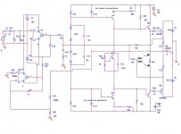
Put a very high value resistor across C5 to reset the integrator when power is off.
If the 470R resistor is burning then both upper and lower driver transistors must be conducting, try and trace what could be causing this.
If the 470R resistor is burning then both upper and lower driver transistors must be conducting, try and trace what could be causing this.
darkfenriz said:is the whole project 'acceptable' ?
That is a metaphysical question.

over voltage at mosfets gates
if you want to avoid wasting money in destructed mosfets, use Zener protection diodes. One between emitter of Q10 and output. Another onebetwwen the output and the emitter of Q? (PNP complementary to Q10). You can use Zener voltage about 2 volts lower than the max rated VGS of the IRF mosfets.
If you destroy zener diodes it costs less than the IRF...
Hi darkfenriz,
Check R24, R25 for open as well as the 0.22R resistors. If you have that much across the 470R resistor, Q10 and it's compliment are either on or could be in reverse E-B breakdown. I'm fairly sure you will find a few transistors shorted. An open PCB connection could change things though.
-Chris
Check R24, R25 for open as well as the 0.22R resistors. If you have that much across the 470R resistor, Q10 and it's compliment are either on or could be in reverse E-B breakdown. I'm fairly sure you will find a few transistors shorted. An open PCB connection could change things though.
-Chris
thanks all
one more question: what will be minimal zener current thru 0.5W 47V zener diode? I have less than 1mA I'm affraid.
BTW: all I wanted from this project was to keep output at low feedback with minimal number of stages. I used inverting mode making summing junction the slowest part of everything by means of pole-zero compensation.
This should work nice in terms of low TIM and little interference with speaker back EMF, especially HF component of this signal. What do you think?
regards
Mr darkfenriz,
you have shown such a "guru" approach on this board when answering other posts, and now you need help? 😎
Anyhow, your design is going to have an awfull PSRR
Redesign it and then we can think about the "problems"! 😉
Regards Michael
PS. the "other issue" is somewhere between U4 and Q1//Q3 stages, and is also part of the "problem" you mentioned! 🙂
thank you Ultima Thule
that's why I use for VAS separate transformer, 2x1000u caps filtering +-74V rail, regulated down to +-53 by lm317/337 and filterd by 2x10u caps.
Making it is so inexpensive and simple, and makes amplifier "don't worry" about PSRR aside from efficiency issue.
Thank you for suggestion, time will tell if it is going to have low noise or not.
best regards
Ultima Thule said:Anyhow, your design is going to have an awfull PSRR
that's why I use for VAS separate transformer, 2x1000u caps filtering +-74V rail, regulated down to +-53 by lm317/337 and filterd by 2x10u caps.
Making it is so inexpensive and simple, and makes amplifier "don't worry" about PSRR aside from efficiency issue.
Thank you for suggestion, time will tell if it is going to have low noise or not.
best regards
Yes that's true, I didn't notice the text "reg.", hopefully the regulated ouput voltage is in the order of uV if you are going to expect reasonable PSRR
A very small diffrence in the supplying voltage will give a big offset voltage too so it is very dependent on a DC servo
Regards Michael
A very small diffrence in the supplying voltage will give a big offset voltage too so it is very dependent on a DC servo
Regards Michael
- Status
- Not open for further replies.
- Home
- Amplifiers
- Solid State
- HELP with an amp please!