just a comment...
by someone who is not an expert by any measure.
But... doesn't it make sense to have an asymetrical layout with a stereo amp? The visual appeal of symetrical layout is something, but it doesn'r really allow for the best performance possible.
If the input tranny is off to one side and the outputs off to the other side, you can route the circuit to help minimize noise, not add to it.
Am I wrong thinking this way?
You are quite right. ther's alot of sense doing everything symmetrical esp when things go wrong on one side it is easier to compare A+B channel test. Looking at amps made decades ago, things where put where fitted. The rule is to keep the front end (input) away from power components and with stereo as you mention both channels look same all is better.
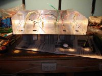
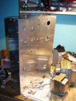
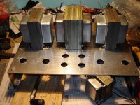
Photo top place stereo power amp 200W amp. The ventilation will need it for sure.
richj
Photo top place stereo power amp 200W amp. The ventilation will need it for sure.
richj
Attachments
This is the real schematic of my working amp
I have to lower the gain, but I dont want to lower Rf. maybe removing the C on R3. what do you think?
thanks to all for helping me 😉
An externally hosted image should be here but it was not working when we last tested it.
I have to lower the gain, but I dont want to lower Rf. maybe removing the C on R3. what do you think?
thanks to all for helping me 😉
Your CCS is still not quite optimum. Assume 2V across the green LED. That leaves you with 5V across the resistor chain. Your LED current must be about 5mA. But you drop almost 5V across the lower resistor (and transistor), leaving precious little resistance up the top to lose any unwanted AC component across. The lower transistor needs to be a small-signal type and only needs 2V across it. Make the lower chain resistor 390R and the upper 680R. This will improve ripple rejection. The small-signal transistor will improve CMRR of the phase splitter.
Removing C3 will reduce gain at low frequencies by adding local stage negative feedback, which reduces thd.. also it's value is quite low and no need for 630V rating as cathode sees only a few volts. Removing it can be controversial, it is part of the closed loop feedback circuit, and it is often said this cap (in this position) has quite an influence on the sound quality. Ironically when omitted some tube amps sound dull. Others use tantalum types but isn't really worth it.
A switch-mode low ESR electrolytic cap is a cheaper substitute and probably more effective.
R3 could be left or standard type 1K6 fitted...
R4 seems wildly high....common pentode circuits in 3 stage amps use between 4K-22K, again this value is determined by the output transformer quality with square wave. So much hangs on o/p tranny quality.
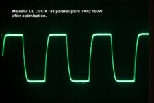
When everything is working as it should be, one should get a square wave of this quality.
ricxhj
A switch-mode low ESR electrolytic cap is a cheaper substitute and probably more effective.
R3 could be left or standard type 1K6 fitted...
R4 seems wildly high....common pentode circuits in 3 stage amps use between 4K-22K, again this value is determined by the output transformer quality with square wave. So much hangs on o/p tranny quality.
When everything is working as it should be, one should get a square wave of this quality.
ricxhj
Attachments
EC8010 said:Your CCS is still not quite optimum. Assume 2V across the green LED. That leaves you with 5V across the resistor chain. Your LED current must be about 5mA. But you drop almost 5V across the lower resistor (and transistor), leaving precious little resistance up the top to lose an any wanted AC component across. The lower transistor needs to be a small-signal type and only needs 2V across it. Make the lower chain resistor 390R and the upper 680R. This will improve ripple rejection. The small-signal transistor will improve CMRR of the phase splitter.
I also don't like to use tip122, because they are high power darlington, and I don't really want that..
so, BC549C is a good choice for lower transistor. What do you recommend for the upper one?
richwalters said:Removing C3 will reduce gain at low frequencies by adding local stage negative feedback, which reduces thd.. also it's value is quite low and no need for 630V rating as cathode sees only a few volts. Removing it can be controversial, it is part of the closed loop feedback circuit, and it is often said this cap (in this position) has quite an influence on the sound quality. Ironically when omitted some tube amps sound dull. Others use tantalum types but isn't really worth it.
A switch-mode low ESR electrolytic cap is a cheaper substitute and probably more effective.
R3 could be left or standard type 1K6 fitted...
R4 seems wildly high....common pentode circuits in 3 stage amps use between 4K-22K, again this value is determined by the output transformer quality with square wave. So much hangs on o/p tranny quality.
When everything is working as it should be, one should get a square wave of this quality.
ricxhj
The low frequency response of this amp is the best that I ever heard, so if C3 improves low f.r., ... I wont take it out. Maybe only for trying, I have 2 channels so I can take one cap off and compare 😀
I will change it to 100uF 50V. R3 to 1K6, R4 to 3.3K+25K pot and measure the square wave and then replace the final value with a fixed R.
Here is the new schematic. Red is "to do"
An externally hosted image should be here but it was not working when we last tested it.
EDIT
R14 has the same value since "my" first design.. maybe I see it now and think that might be a little low.. am I right?
MJE340 or TIP51. Anything that can stand the voltage, really. Even an enhancement-mode MOSFET will do (although you than need to drop more voltage across the lower resistor in the divider chain, which isn't ideal in your application).
I'd just bung a fixed 200R resistor in as your current programming resistor unless you're going to tweak that stage for maximum output as viewed on a 'scope.
I'd just bung a fixed 200R resistor in as your current programming resistor unless you're going to tweak that stage for maximum output as viewed on a 'scope.
zafira1981 said:
The low frequency response of this amp is the best that I ever heard, so if C3 improves low f.r., ... I wont take it out. Maybe only for trying, I have 2 channels so I can take one cap off and compare 😀
This can be deceptive.
1.You mention best LF response. This can happen because there may be too little global nfb at the LF end, this creating higher bass harmonics, and the speaker sounds fuller because driver has less damping by the amp as the loop gain has run out at the LF end.
2. OR you mention the LF frequency range is very low i.e below 20Hz or so.
Which one is it ??
richwalters said:
This can be deceptive.
1.You mention best LF response. This can happen because there may be too little global nfb at the LF end, this creating higher bass harmonics, and the speaker sounds fuller because driver has less damping by the amp as the loop gain has run out at the LF end.
2. OR you mention the LF frequency range is very low i.e below 20Hz or so.
Which one is it ??
I dont know. I will add to my "to do" list to test and measure the amp with LF senoidal input.. like 10hz
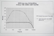
richwalters said:Assuming everything is working, have you thought of plotting the open loop gain and response ? encl example. Excel program is ideal for this.
richj
another thing to add to my "to do" list 😀
thanks!!!
zafira1981
I forgot to reply regarding reducing amp gain. This OMO but depends how much you want reducing. If 3-6dB I'm tempted to increase global nfb, advantages even lower thd and noise. Don't, reduce it without an os' scope as as any change will result in ringing on square wave and will require a compensation cap change on the 1st stage..some experience is required.
If you <check out> a tube amp at 10Hz by forcing a sine wave through it at full power below the output transformer design cutoff frequency will probably saturate and overload the output tubes. This is bad practise.
Alot of p-p tube amps behave poorly below o/p tranny cutoff usually 6dB/oct. Lowest note in music is lowest organ note at 16Hz and no commercial amp/speaker system can manage this.
richj
Just ran across this old thread and the pictures are all gone. Can anyone upload at least the final schematic? Thanks.
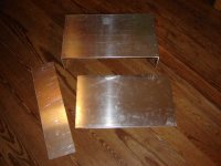
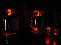
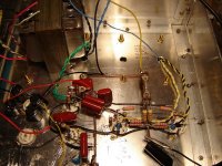
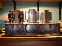
Hello!! how are you? Sadly I never finished the amp. It sounded amazing. I never moved from prototype to a good looking amp.
I will try to find the final schematic. 😀
I will try to find the final schematic. 😀
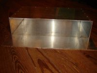
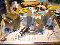
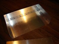
some pics...
Attachments
-
 DSC01884.JPG56.4 KB · Views: 107
 -
 DSC01883.JPG41.8 KB · Views: 91
 -
 DSC01881.JPG51.8 KB · Views: 85
 -
 DSC01877.JPG25 KB · Views: 112
 -
 DSC01878.JPG70 KB · Views: 110
 -
 DSC01876.JPG25.2 KB · Views: 145
 -
 DSC01875.JPG31.5 KB · Views: 148
 -
 DSC03392.JPG37.5 KB · Views: 154
 -
 DSC03388.JPG95.3 KB · Views: 138
 -
 DSC03384.JPG79.2 KB · Views: 152
- Home
- Amplifiers
- Tubes / Valves
- Help with amp layout