The first option - here's a more simple way of describing it:
View attachment 1060251
That exact filter would make wonders with my setup. Or with any system, that includes multiple woofers in an open baffle configuration.
Resistive voltage divider seems like a rather simple solution, is there any ''catch'' to it? I haven't seen it in use in active filters. First order might be too shallow to counter the rising LF response, and it might require to move the crossover point somewhat lower. No need of signal inversion, at least that I know of.
Your purple trace actually requires a biquad rather than a first-order filter. With a biquad, you can make this:
When you design a Linkwitz transform circuit (popular type of biquad) for Q = 0.7071068 and cut-off frequencies of 79.43282347 Hz and 125.8925412 Hz, this is what you get. See also the attachment.
Attachments

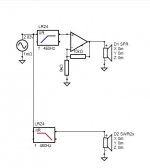
Marcel was a bit quicker than me.Quick and dirt, but it gives you some idea what can be done .View attachment 1060451View attachment 1060452
Your purple trace actually requires a biquad rather than a first-order filter. With a biquad, you can make this:
View attachment 1060534
When you design a Linkwitz transform circuit (popular type of biquad) for Q = 0.7071068 and cut-off frequencies of 79.43282347 Hz and 125.8925412 Hz, this is what you get. See also the attachment.
Thanks for answering. I didn't know that such a ''sharp'' FR correction was possible with a single op amp circuit. If so, I could perhaps correct for the whole LF cancelation issue, without further corrections in digital domain.
I've managed to tweak a Linkwitz transform filter within Vituix and extend the frequency response all the way to 40-50Hz. However, with a biquad, I only see the option of boosting the low frequency response (Unlike the example in Marcel's graph).
Presented values: Fo 20Hz ; Qo 0.3 ; Fp 45Hz ; Qp 2
Is it possible to design the biquad for these values?
Looking at the instructions from Siegfried Linkwitz's site (link https://www.linkwitzlab.com/images/graphics/f0Q0fpQp.gif) - Calculated K value from those parameters is a negative value.
If you simply build/draw the Linkwitz Transform schematic in VituixCad, and set the desired transfer function of the LT in the Optimizer, you can have the VCad Optimizer do the work for you and optimize the component values.
I can't seem to figure that one out, but I did find a transform filter calulator by mr. SL.If you simply build/draw the Linkwitz Transform schematic in VituixCad, and set the desired transfer function of the LT in the Optimizer, you can have the VCad Optimizer do the work for you and optimize the component values.
Managed to get a combination that gives positive K. However, those numbers seem relatively high - by using 2 uF capacitor as a C2 value, I would need to get electrolyric caps for values C1 and C3. If a smaller C2 cap is used (0.2uF), I could use film capacitors on all three places, but then R2 value states 17 kOhm. Would such a high resistance degrade the performance in any way? Are those ''common'' values, or I am exaggerating the filter slope?
Probably I was not clear: you simply build the LT in Vituixcad with Opamps, resistors and capacitors, starting with the R and C values Linkwitz gives on his website. Then you define a target, that is a desired transfer function of the filter and let the Optimizer optimize the R and C values in the schematic. It is not necessary to work with filter coefficients.
why have you specified q of 0.3?Presented values: Fo 20Hz ; Qo 0.3 ; Fp 45Hz ; Qp 2
Is it possible to design the biquad for these values?
Looking at the instructions from Siegfried Linkwitz's site (link https://www.linkwitzlab.com/images/graphics/f0Q0fpQp.gif) - Calculated K value from those parameters is a negative value.
I must say, that's one wonderful piece of a software. Thanks for being persistent, I managed to get the filter fine tuned it. 🙂By toggling/playing with the values of the capacitors and resistors in Vituixcad you can experiment and taylor the circuit. The filter andf SPL displays will immediately show the effects.
One other thing that poped out - phase change, due to linkwitz transform circuit, totally messed up the phase response of a LR 24 dB/Oct crossover. It was in phase right at the crossover frequency, but just 20 Hz up/down, there was a significant cancellation between drivers. Changing the polarity of one of drivers did make response somewhat better. I guess the crossover point might be too close to the biquad filter. Either way, I'll put it together and give it a try.
It gave a good result from simulations.why have you specified q of 0.3?
Most of my project is based on Linkwitz's ideas on (in my case - somewhat) constant directivity and ''lesser room interaction'' speaker. I acquired two pairs of 12 inch woofers (two per speaker), but with relatively low xmax. If I am to extend them down to 40ish Hz, they would need a really steep rolloff - hence the parameters from the post above.
For bass extension, you can also use this circuit. It has the advantage that it needs only two capacitors of standard values, and the disadvantage that the calculations are more complicated than those for Linkwitz's circuit. The values given are for extending a loudspeaker with 80 Hz, second-order Butterworth response to 40 Hz. Of course the op-amp supply pins need to be connected to something.

Some remarks: whatever final boosting schema you will apply, woofer distortion will skyrocket below 100Hz with 10-15 dB boosting.
Many mistakenly will take for "impressive bass", but it is not. This is the nasty part that is hardly ever mentioned in LT context.
And lastly: room modes will dominate the final in-room results, much more than any chosen low end just-speaker response.
Many mistakenly will take for "impressive bass", but it is not. This is the nasty part that is hardly ever mentioned in LT context.
And lastly: room modes will dominate the final in-room results, much more than any chosen low end just-speaker response.
For bass extension, you can also use this circuit. It has the advantage that it needs only two capacitors of standard values, and the disadvantage that the calculations are more complicated than those for Linkwitz's circuit. The values given are for extending a loudspeaker with 80 Hz, second-order Butterworth response to 40 Hz. Of course the op-amp supply pins need to be connected to something.
View attachment 1061370
Thanks for recommending it. I will input it in VituixCad with those exact values and start changing one at a time.
Some remarks: whatever final boosting schema you will apply, woofer distortion will skyrocket below 100Hz with 10-15 dB boosting.
Many mistakenly will take for "impressive bass", but it is not. This is the nasty part that is hardly ever mentioned in LT context.
And lastly: room modes will dominate the final in-room results, much more than any chosen low end just-speaker response.
About the distorsion issue - How about, instead of active circuitry, adjusting the FR digitaly (Rew eq and then via convolution to a streamer)? I simulated that as well, it removes up to 10 dB of higher frequency (over 250 Hz) response. Would you say its a better way of achieving the same?
One other thing, that would require gain adjustment of a secon driver. Could it be done just with a simple filter as this one?
Attachments
If you know the desired pole and zero positions, you can calculate the values for the filter of post #31 with the method in the attachment. I intended to do the calculation for the transfer of post #21, but the desired transfer function had changed before I got a chance to do the calculation. In any case, numerical optimization should also do the trick.
Attachments
@ distortion issues: that problem cannot be fixed unless you resort to so called Motional Feedback.
Otherwise: more woofer excursion because of any type of LF boosting= more distortion.
Otherwise: more woofer excursion because of any type of LF boosting= more distortion.
@ distortion issues: that problem cannot be fixed unless you resort to so called Motional Feedback.
Otherwise: more woofer excursion because of any type of LF boosting= more distortion.
Would there be a large distortion, even if the woofer is operating within it's xmax?
Is it possible for an intermodulation distortion to appear between 60 Hz and 400 Hz waves?
It seems that a midbass driver would be an ideal solution for this situation.
Here's a circuit I've been experimenting with. https://sound-au.com/project197.htm Figure 3. Bass boost plus 12 dB/octave bass rolloff. "Q" can be altered with only one resistor. "Q" affects how much bass boost is introduced.
I'm still experimenting with it. Variable "Q" can be added with a potentiometer. As with all equalization, less is more.
My everyday preamp has cascaded filters; Boost below 80 Hz cascaded with a 20 Hz 36 dB/octave high pass filter. It works extremely well but uses a lot more parts and board space - 3 op amps and a large handful of bulky and expen$ive Wima film capacitors.
Would there be a large distortion, even if the woofer is operating within it's xmax?
Any time you increase excursion, you increase distortion. Speakers are the primary source of distortion by far in a well set up system, even a modest system. Look for woofers with "shorting rings" in the magnetic circuit. They offer the lowest distortion, and improved impedance vs frequency curve. They can also offer modestly improved midrange extension.
You have the right idea, paying attention to xmax.
- Home
- Source & Line
- Analog Line Level
- Help with active filter design