Hello everybody,
I'm an tube guy, quite old now. And I have some problems to understand complex SS circuitry (for me), as in DC coupled amps.
I have an old InterM Powered mixer (from 1985, 1635 model), which needed a power supply & amp board recap.
Once the cap job done, every preamp channel in the mixer worked fine. The left channel amp was OK too, but the right one sounded weak with a lot of distorsion. For me the sound is like earing a tube amp with a bad tube preamp's cathode decoupling capacitor.
I need some help to understand how this amp works, and where to look in order to repair it. I join boths schematics, with measured voltages.
I've checked every small transistors (desoldered) with a cheap chinese LCR meter, and they seem to be good. There is no blown fuse at power up, and no protection mode ie : the output relay closes on each channel.
A quick diode test on each power transistor (2SC3856 / 2SA1942) give the same results on each board, so I assume that they are not bad.
There is also the same output voltage on each board : 12 mV.
Every resistor tested OK, as with the capacitors, exept two on the right board : C202 100pF, Silver mica, and C208 50p, SM too. I replaced them, but the right amp is still weak and distorded. the diodes are all good too.
I'm not sure about the problem : a bias problem, a driver problem ? The voltages seems to be bad around this stages, and I don't see the +/- 0.5V bias voltage on the base of the output transistors.
I am able to repair simples SS amps, as soon as I familiar with the circuitry, but this one is a bit too complex for me ; I can't understand how the pnp differential amp works, for example...

forgotten schematics
Sorry, I was supposed to join the schematics...
left amp board
View attachment left amp board.pdf
Sorry, I was supposed to join the schematics...
left amp board
View attachment left amp board.pdf
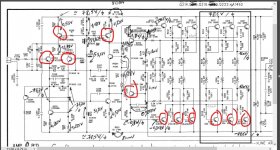
Hmm... those diagrams are full of errors.
Many of the transistors are drawn incorrectly orientated. For example, Q201 and Q206 have the emitter and collector reversed. The same applies to all the PNP output devices. Emitter and collector are drawn incorrectly.
You can check the Vbe multiplier (bias generator) by seeing if the voltage across Q208 varies as the preset VR201 is turned.
Compare the voltage with the good channel. I would expect around 2.6 to 2.8 volts or so to be needed before the output stage conducts.
Low bias alone though would not give weak and distorted sound.
All the ones I have marked are incorrect.
Attachments
Yes, indeed, but as I have all my time to repair it, this anchor will just not finish in the trash bin. And even for the cost of replacing all the transistors & caps, I doubt to find a new good class AB powered mixer. I could surely find a new Behringer's class D mixer, but :
my left channel sounds just fine, everything in the mixer works, and the DSP doens't sound like crap, I mean not like in some cheap Behringer's powered mixers... No offense for Behringer or class D amp, they just can't compete.
my left channel sounds just fine, everything in the mixer works, and the DSP doens't sound like crap, I mean not like in some cheap Behringer's powered mixers... No offense for Behringer or class D amp, they just can't compete.
Hmm... those diagrams are full of errors.
Thanks, I'll will check the Vbe this morning (6 AM in Reunion island). I didn't noticed the errors, cause I just focused on checking and measuring all components & voltages. Also I'm not so familiar with SS amps, as I said before, no problems with voltages amplifiers.
well, Reunion Island. You probably don't have the wealth of used equipment on e-bay to select from that we have on the mainland. Flying in components in little boxes would be a lot cheaper than whole pieces of equipment.
A bit of generalization. A lot of dropout problems in old transistor circuits, due to the low voltages used, is oxidation on the connectors. These can often be "repaired" by removing and replacing to scrape the oxide off the tin or brass. that is why we suggest you check the amp circuit direct with a 1 vac signal before diving into it; all the interboard connectors in the mixer part and especially the wipers on all the pots are subject to this age oxidation problem. Corrosion is particularly pernicious near the sea, there is salt in the air.
Another common problem is dried up electrolytic capacitors. If for example you injected a radio earphone signal into Q202 base with a pair of alligator clip leads, and still had distortion, I would change c207 and c208, even if they tested okay at the 2 v a ESR meter or capacitance meter tests them at.C211 & C212 are also suspects. Of course, check the rail and op amp power voltages, electrolytic capacitance failure there is common and often zener diodes & the voltage regulator IC's that use them internally fail. Plastic film caps and ceramic disk caps are not very prone to failure due to age. the wiper on VR201 is also subject to dropout due to oxide buildup. I don't see a protection relay in this schematic to have oxidation on the contact cause sound dropout.
Transistors hardly ever fail except the output ones can overheat due to shorted speaker connectors or a shorted speaker coil, or a clogged up fan & fins. If you have weak sound, that is probably not the problem.
Resistors are as likely to get dropout as transistors, that is rare but can occur. In that case you have to trace the sound (ac voltage) through the circuit to see where the ittermittant occurs. Again, I exercise circuits with the earphone jack of a FM radio turned down to 1 vac and look at AC voltages flowing through. If you don't have an oscilloscope, a cheap analog meter with 2v and 20 v AC scales can be useful. Put a .047 or .1 uf cap in series with the negative probe to speaker ground, AC scales on analog meters will false positive respond on DC signals.
One warning about coastal equipment. The US navy forced resistor manufacturers to use a special non-porous paint on their resistors starting about 1960. European equipment did not get this paint until later, and high value resistors could get moisture incursion that lowers their value. These problems will show up as a low value on a meter, typically.
Last edited:
To Turk 182,
Yes I have. The left amp is OK, and I need to try the defective channel's EQ bypass.
I wasn't able to try it yesterday, due to a the power plant suddenly on strike... During all the day. I just hope that this will not be the case today.
Sorry for the delay.
With the corrections given to the schematics, I've a better understanding of the PNP LTP work. Comparing it to a tube LTP, It's not so different. I still need advices about the remaining stages, IE the class A amp and the DC coupling of the remaining stages.
Anyway, I'm thinking of changing all the transistors, it will be quicker to repair, but I will not understand how this amp works.
Hello,
Well, Indeed it would have been great to have the choice about used lab equipment as in your country !
Anyway, my lab is quite well equipped : at least several oscilloscopes (max 50 Mhz) and frequencies generators, power supplies, high and low voltages (dual for these ones), good flukes multimeters, and hakko soldering / desoldering stuff. And of course a tube tester.
I'm quite confident about the power supply : all the electrolytic capacitors have been replaced with good ones, from Nichicon and / or Panasonic brands, low ESR & long life types. And the same for boths amplifiers boards.
I don't think the power supply to be faulty : It's common to boths amps and preamp, and the left amplifier board works fine.
For C207 and C208 : I've found them both blown in the right board, so I replaced with two good ones, exept that they are high voltage rated. That was the only capacitor fault founded in the defective amp board (every capacitor tested desoldered). C211 and C212 were replaced by Panasonic new ones in both boards, so I assume they are good.
I've checked also every resistor, all were fine, even with this surface corrosion you described.
I've checked each small transistor, all tested OK, but I didn't compare the hfe tests results with the datasheet.
For the output stage transistors, I've desoldered only two, an output PNP and a driver ; they were OK on test, but I didn't compare the Hfe results with the datasheet. For the remaining transistors, I did a diode test, and compared my results with the left board : everything was the same. So I've assumed that the output transistors were fine.
I've a protection circuit in both boards, which don't activate the output relays, in case of DC detection on the output coil. They works fine on each board, and there is the same DC on each board output, around 13 mV.
That's why I thought that the output transistors were OK.
I've to test the right board with direct signal injection, IE with the preamp bypassed, and I will check the signal with my scope. But yesterday I had to stop, due to a strike in the power plant... All the day !
I had just begun to see a correct signal in the LTP, befor the shut off.
Today, I can't test more, because I'm not at home, but I will tomorrow, and give you some results.
thanks all for the help and interest.
As I said previously, small signal transistors in amps do not fail frequently. Television horizontal driver transistors run at 90% of rated power all the time, and the thermal cycles tend to cause those to fail after a defined number of years. Music has a crest factor of about 5%, amp transistors do not thermally cycle that hard, and except for output transistors that are damaged by speaker shorted turns ,shorted wiring or clogged fans, amp transistors don't fail much. Some designs have inadequate heat sinks on the output transistors for the rated wattage. Defective welds do happen about 1 in 10000000000, but resistors diodes & film capacitors have about the same failure rate from the same defect. I've small signal transistors from 1970 happily performing for 18 hours a day in my main amp. The hundreds of small signal transistors and signal diodes in my 1968 Hammond and 1966 Wurlitzer organs are all fine. Every key has 4 diodes in some transistor organs with 122 keys, and I know of ONE that a diode opened up after 40 years: Due probably to a bad weld. Exception little white Japanese transistors from about 1970, those were known dogs. So take data on where the failure is to find the defective part, don't shotgun replace transistors, diodes, resistors, or film capacitors. Output transistors are suspicious in amps that are set up and torn down at every gig, due to the many wiring problems, especially if 1/4 phone plugs are used for the speakers. Those get pulled out a lot, which causes a short. In amps, the b-e junction should be plus or minus 0.6 v depending on polarity, and the c-e voltage should be somewhere between 1/4 and 3/4 of the rail voltage. Frankly solder joints made by humans are more suspicious than the small signal transistors. There are always brands that exceed power current or SOA ratings on transistors, those design faults can cause failure. Drivers transistors are frequent candidates because the vendor is too cheap to install a heat sink.Anyway, I'm thinking of changing all the transistors, it will be quicker to repair, but I will not understand how this amp works.
Last edited:
Hi,
I've taken & compared the Vbe of each transistor in boths amps.
I Join the schematic with measured voltages in the left amp (good one) ; above the schematic you'll find the measurements for the defective unit (right amp).
I'm not sure, but I suppose that the transistors Q209 / Q2010 & Q211 / Q212 are at least bad. Does they compose the driver's unit ?
And what to think about the output transistors ? Is it correct to suppose that their Vbe = 0V is due to the driver stage , or are they also defectives ?
Q209/210 are part of the protection circuit and can be removed from the circuit as a test. A good amp will function without them.
Q211 and Q212 are the drivers.
Power transistors usually fail by going short circuit and the fact you have got no DC offset at the output suggests they are OK.
Did you test the Vbe multiplier as I suggested in post #6?
Q211 and Q212 are the drivers.
Power transistors usually fail by going short circuit and the fact you have got no DC offset at the output suggests they are OK.
Did you test the Vbe multiplier as I suggested in post #6?
Sorry
Again, I've forgotten the schematic !
You posted that while I was typing my reply above
")
If you have 400mv across the B-E junction of Q209/210 then you appear to have a very high bias current flowing. So something doesn't add up there. I suspect they may be another error in the circuit and that a couple of resistors biasing those protection transistors have been omitted.
Check the DC voltage across each of those 0.47 ohm resistors. There should only be a few millivolts across each.
Hi,
No it's an error : the Q209 & Q210 voltages are both 40 mV and not 400mV.
I mean at the left & good amp. At right amp, Vbe for Q209 & Q210 is 0mV
And I've not testet yet Q208, the Vbe multiplier, because if the problem comes from another stage, I don't want to modify the bias voltage.
No it's an error : the Q209 & Q210 voltages are both 40 mV and not 400mV.
I mean at the left & good amp. At right amp, Vbe for Q209 & Q210 is 0mV
And I've not testet yet Q208, the Vbe multiplier, because if the problem comes from another stage, I don't want to modify the bias voltage.
Last edited:
For the 0.47 Ohm resistors :
- on the left side there is something like 3.8 mV across each
- on the right side : 0mV ; so there is no current flowing through the output transistors on this side.
The Vbe multiplier is good on boths amps : as soon as I move VR201, there is a Vce change.
Vce of Q208 are : 2.35V on the left amp, and 2.325V on the right, at power on
- Status
- This old topic is closed. If you want to reopen this topic, contact a moderator using the "Report Post" button.
- Home
- Live Sound
- PA Systems
- help with a defective InterM amp board