Be sure that the output tubes grid stopper resistors, and screen stopper resistors . . . are connected Directly to the tube socket Tabs.
Extra wire from the resistors to the Tabs does not count as grid stoppers and screen stoppers (Wire has inductance).
At the crest of the sine wave:
One tube's plate voltage is Much Lower versus the screen voltage;
While the Other tubes plate voltage is Much Higher.
Then for the opposite polarity at the crest of the sine wave:
The tubes change which plate is Lower, and which plate is Higher than their respective screens.
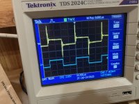
Interesting. I noticed that the step voltage on the plate aligned at the peak of the grid drive signal. I decided to try driving the amp with a square wave signal. All is revealed. See attached. Blue is grid drive Yellow is plate voltage. There is massive ringing on both the rising and falling edges.
Of course, for convenience, I have put the grid stop resistors, along with the rest of the grid drive components on a small PC card to help keep the circuit layout "clean". (Clean is relative!). I have about 2 inchs of wire from the 1K resistor on the PC card, to the tube socket. I didn't fix the schematic but I have removed the resistors connected to Screens (G2). Should I put small 0.1 or so caps from screen grids to gnd, right at the tube socket? How to address the grid drive signal? RC filter right at the tube socket with cutoff at around 25KHz?
Of course, for convenience, I have put the grid stop resistors, along with the rest of the grid drive components on a small PC card to help keep the circuit layout "clean". (Clean is relative!). I have about 2 inchs of wire from the 1K resistor on the PC card, to the tube socket. I didn't fix the schematic but I have removed the resistors connected to Screens (G2). Should I put small 0.1 or so caps from screen grids to gnd, right at the tube socket? How to address the grid drive signal? RC filter right at the tube socket with cutoff at around 25KHz?
Attachments
Wow!
Are both plates giving the same large overshoot?
That is important to know.
You disconnected the negative feedback, Yes or No?
During testing, you are using a Non-Inductive resistor across the 8 Ohm secondary tap, Right? . . . Not a wirewound 8 Ohm resistor.
Perhaps a couple of series RC Snubbers will overcome the large overshoots. Plate 1 to center tap, plate 2 to center tap.
I do not normally care for snubbers. Usually a Band-Aid at best, with additional tradeoffs.
Perhaps a different output transformer will give a better response, you need one to try it on one channel, just to verify the possible cause of the problem.
First I changed the grid stoppers to 10K, soldered with short leads to the tube socket. No change, still the ringing on square wave and step at the peak of the sin. I dug out the schematic from the RCA Victor V301 radio phonograph and found in the original design they have 0.0025 MFD from the plate of each output tube to gnd. I am attaching the schematic. These guys were near genius back then I figure. Everything was practically new territory. I suspect it may have something to do with the design of the OPT. I did the same and the problem is solved. Everyone - thanks for your assistance.
Attachments
Not so fast. Snubbers problematic. I had really bad ringing when I tested the amp with square wave input. Initially I tried snubber capacitors from plate to ground on the output tubes. It didn't work very well. Sensitive to input frequency and loading with 'scope probes. What did work was changing the feedback from pure resistance to an parallel R-C network, such that feedback increases with rising frequency. I may have been a bit heavy handed, the rolloff starts at about 10kHz, but the square wave response is now just slightly underdamped with a very small overshoot that recovers nicely. I'll post a photo later. At my age I don't hear much above 10K !

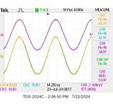
Attached is the 'scope screen capture of 1 kHz power into 8 ohm resistive load, followed by sq wave response. Violet is output, Yellow and blue are the grid drive signals, one is inverted. Square wave plot shows smallest amount of overshoot.
Attachments

Series RC snubbers are not easily calculated to find the optimum values.
That is because of the unknown amounts of:
primary to secondary leakage inductance, and the amount of primary distributed capacitance.
There are other parasitic capacitances that apply too, primary to secondary, primary to laminations, secondary to laminations.
Getting close to optimum requires some guessing, patience, and experience.
Fortunately I was able to get rid of the snubbers by tailoring the feedback network. See earlier post #25.
1. The 6BG6 Beam Power tubes are a current source that drives the output transformer primary.
They are a high impedance connected to the primary taps.
That lets the resonances of the transformer sort of "flap in the breeze"
Applying negative feedback makes the Beam Power tubes a resistive source that drives the transformer primary.
That means the 6BG6 are no longer a current source; but that was only because the negative feedback error term reduced the plate impedance.
All the way around the global feedback loop . . . it works better at mid frequencies, but not as well at high frequencies.
2. Driving the same output transformer primary with triodes, the low to medium plate impedance intrinsically Prevents the resonances of the transformer from "flapping in the breeze".
This is a key test.Find out if the full kink happens when the Plate is reaching maximum voltage or when the Plate is reaching minimum voltage. Maybe the Plate is getting too low and hitting Ground?
If the kink occurrence is at minimum plate voltage....
Watch the output tubes G1 voltage relative to the cathode voltage when the kink happens. If G1 has stopped being negative relative the the cathode voltage when the kink happens then the output tube is full saturated and has no more current to give. Clipping is now happening.
richgwilliams and Bluesystems,
The typical action of both Beam Power tubes, and Pentodes is similar under these conditions:
When the plate voltage is low, a higher voltage screen's current is high. Think of the screen at 300V as if it was "Plate number 1",
and the plate at 50V is "Plate #2"
So, when the Real plate is at 50Volts, and the screen is at 300V, where to you think a large portion of free electrons are going to go? . . . Right!.
Also, when the plate voltage is near 50V, the plate is Ohmic, it is Not Constant Current.
With the plate voltage at or near 50V, then for control grid voltages of 0V and/or all the way to several 10's of volts negative, the plate current is a very steep curve (such as a low rp triode; a JFET in the Ohmic region; or a MOSFET in the Ohmic region.
Just to make that visually clear, please take a look at the second graph of the following 6L6GC data sheet:
6L6GC.pdf
I hope that is enlightening.
Ok I understand as the higher voltage screen "steals" electrons from the lower voltage plate plate current is reduced and screen current rises.Just to make that visually clear, please take a look at the second graph of the following 6L6GC data sheet:
That makes perfect sense and explains the first drop in plate current and rise in screen current.
I also see the steep drop in plate current at lower plate voltages at bias levels from zero volts to maybe -10 volts on G1.
However I thought a snivet was the result of a area of negative plate resistance causing oscillation in the output tube.
Is this incorrect? Snivets seem to produce a lot of variation in explanation and that often suggests the correct answer is a bit obscure or confusing.
A mystery part to me is why as the plate voltage continues to go even lower does the screen current begin to drop back down and the plate current start to rise up gain? This is negative plate resistance.
Common sense suggests as the plate continues to drop toward zero volts the screen current should keep rising and plate current falling but this is not what happens it seems at more negative G1 bias levels.
For some reason at higher levels of negative G1 bias the plate current starts to rise again at at very low plate voltages before dropping again at zero plate voltage. This is a area of negative plate resistance and I understood was the cause of the oscillation that is referred to as a snivet.
So common sense is not fully useful and perhaps there is a bit of physics missing in my understanding.
I found this application note from RCA on Snivets.
This suggests there is more than one effect responsible for the RF interference and that my understanding is not there yet.
This suggests there is more than one effect responsible for the RF interference and that my understanding is not there yet.
Attachments
Last edited:
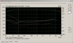
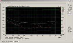
Since ARTA is free download, I thought it would be interesting to see how this amp performs, 1) given that the OPT is very limiting, and 2) seeing that the ringing problem with square wave input has been resolved. I ran two frequency response and distortion tests. First test at 1 watt and second test at 5-3/4 watt. The I/O "sound card" was one of these $5 USB dongles about as big as your thumb with a 1/8 in headphone and microphone jack. I should have run the test "loopback", to see the performance of the dongle itself. Next time. Results attached. Distortion is significant at the higher power test, especially below 100 Hz. I didn't try to calibrate the I/O. I just made sure that ARTA's meters did not indicate an overload on the microphone input.
Attachments
The transformer does look to limit the low frequency power a lot as 5.75 watts from basically a pair of 6L6 with a 440 volt rail is a little low on power.
Good it is self bias to help protect the output tubes as the peak current in the transformer will be very high at low frequencies as the transformer saturates.
If you are still getting about 18 watts at 1Khz then over all considering the transformer used you seem to have done well for your efforts.
Can you post a picture of the amplifier? Always interesting to see how people go about building stuff.
Great fun.
Last edited:
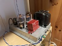
Well, since you asked so nicely, photo attached. FYI, the chassis is from an old Admiral TV set. The TV had 2 chassis. The one in the photo consisted of the main PT, two chokes, and provided two HV supplies as well as the usual 5v and 6.3v filament supplies. It also contained a single ended 6V6 amp for the audio. The other chassis had everything else and is where I got one of the two 6BG6 output tubes. Murphy's Surplus, El Cajon, CA is a great outlet for stuff that likely hasn't been touched in 50+ years. I picked up a few tubes for $1 a piece.
Since I have come this far, and it's working about as good as can be expected, I just bought on ebay a "Not working - for parts or repair" Hammond Organ amplifier, AO-63. It looks to have a massive OPT, it may have been a 25-30 watt amp. Uses 7591 output tubes, +450v to the OPT. I'll see what a decent transformer makes of this amp.
I have a tendency to be impatient, at least it has tempered a little bit in old age. I wound the anode spring connectors out of a scrap of 12 gauge Romex. I was pleased at how they came out. I need to pot them in silicone before I electrocute myself!
Attachments
Great job and nice looking repurpose of used material.I just bought on ebay a "Not working - for parts or repair
I always feel a special sense of accomplishment when I make something useful out of stuff that looked like junk to someone else.
Definitely put a priority on getting the plate caps and wiring insulated. Stuff happens so quick.
Ceramic plate caps are about a dollar online from china.
It seems you have succumbed to the DIY bug. Life will never be the same.
BYW
Using matched output tubes can drive down distortion a lot. Something to consider in future projects.
If the idle current in the tubes is off by a lot the transformer low frequency performance will suffer.
You could consider sometime to split the cathode bias resistor and capacitor to be separate for each tube.
Resistor value needs to double when this is done. When the cathode bias resistor is split much larger cathode bypass capacitors are usually needed or low frequency power and distortion will suffer.
The split will tend to move the tube currents toward each other and provides a easy way to measure how matched the tube bias currents are.
It also make you amplifier a handy test jig for future tube matching of power tubes.
Last edited:
- Home
- Amplifiers
- Tubes / Valves
- Help with a 6L6 PP design