Hey diyAudio!
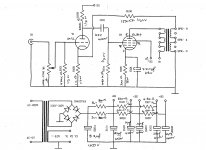
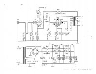
I recently purchased a douk audio 6N2/EL34 tube amp kit to dip my toes in the world of tube power amplifiers. It arrived, and I built the kit, however there was absolutely no sound from either of the output transformers. I (probably retrospectively should have looked through the schematic and tested the PCB, but waiting nearly a month for shipping and my eagerness got the better of me). When I did sit down to crunch the schematic, it seems like there are some unusual things happening around the power stage for a single ended amp (in comparison to the other SE EL34 schematics I was referencing). I was hoping you good folks could take a look and see if there are any major errors in the design of this. I tested all of the resistors and capacitors before building the PCB and they were in spec. Just wanted to verify that there were no design errors before I went ahead and bought some replacement tubes.
Quick note: on the schematic, I have written in pen what connections to the tube sockets the PCB traces had using a multimeter set to continuity, but comparing it to a normal EL34 data sheet it looks like the socket may not be wired correctly.
Thanks in advance!
Attachments
Can you make a photo on printed board? It seems EL 34 is bad connected indeed.
Look at this
Look at this
Last edited:
393/5000
Check the voltages on points B1-B2-B3 + and indicate the values.
check EL34 pin 6 ... if B1 is missing you must make two jumpers on the primary also check the voltage on pin 1 and indicate the value
Indicates the voltage present on points 1-6 + 3-8 of 6N2 ...
On the secondary it checks if there is no jumper between 4 and 8 ohm.
Take a photo of the assembly and the transformer TU
Excuse my English
Thank you all for responding. I thought it looked a little off from the datasheet as well. Gheo23, was that a successful amplifier design? I might just take all of the components that were shipped with this kit and follow another schematic if someone can attest to it working well for an SE amp.
I will post pictures of the PCB as well as scans of the other papers they sent in the morning.
Thanks once again
I will post pictures of the PCB as well as scans of the other papers they sent in the morning.
Thanks once again
What test gear do you have? A scope and sig gen would help here but start off with the first rule of fault finding - in a suitable God like voice.... "Thoult shall check voltages" Start off with HT/B+ then check all anodes, cathodes etc. Some tips, if a valve is conducting then voltage on one end of a anode or cathode resistor will be different to the other end, IE if current is flowing there will be a voltage drop across the resistor. Tip 2 do you have a voltage across g1 and cathode?
Second, check connections, then re-check, then check again, make sure you haven't done anything daft like getting a 10r and 100r or 10k resistor mixed up.
Third, stick a sine wave in the front end then follow it though, sine wave on g1V1? Is the sinewave coming out the V1 anode or whatever? If no sig gen and scope use something like Soundcard Scope a free PC based bit of software, make sure you don't overload the PC's soundcard though by sticking 300v up it's pipe.
Andy.
Are you counting the pins in the tube socket correctly? You should count clockwise from underneath.
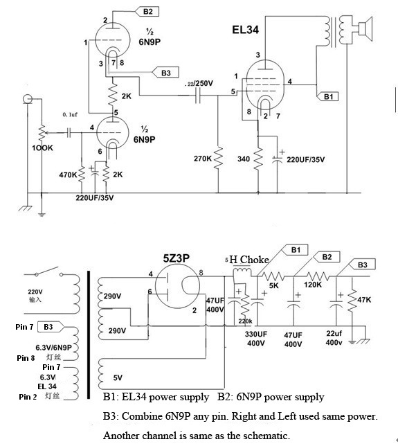
Pins EL34 are not the same, acc. schem....... 2 and 7 - heating...... 3 is plate....4 is second grid....5 is first grid......8 is cathode and 3 grid. Your first grid is not connected.
Last edited:
Hello everyone and thank you for all of the responses. I got home late from work today and did not have a chance to pull out the scope and multimeter to trace the waveforms or voltages, but I will have it done tomorrow. I was getting power to the filaments for all three tubes.
On another note, I miscounted the pins of the EL34 from the top of the socket and not the bottom of the tube (mirrored) so the numbers on the schematic posted are wrong. I will post an updated one in the morning alongside pictures of the PCB/traces and the B1/B2/B3 voltages.
Thank you once again all for replying. Have a good weekend
<<Gheo23, was that a successful amplifier design?>>
Not necessarly.The internet is full of different schematics and this is one of them, a good one I presume, but my advice, pay atention on output transformers.This is a real problem in SE amplifiers.
Not necessarly.The internet is full of different schematics and this is one of them, a good one I presume, but my advice, pay atention on output transformers.This is a real problem in SE amplifiers.
Wrong wiring is found in the power stage:
EL34's Pin 1 is for the suppressor grid and Pin 8 is for the cathode.
Pin 6 is for nothing. The plate is actually Pin 3.
In this circuit you've used grid 2 as the grid 1, which requires driving current and cannot be driven by a single 6N2.
EL34's Pin 1 is for the suppressor grid and Pin 8 is for the cathode.
Pin 6 is for nothing. The plate is actually Pin 3.
In this circuit you've used grid 2 as the grid 1, which requires driving current and cannot be driven by a single 6N2.
Hello everyone,
I finally got a chance to start testing my board. First of all, I'd like to mention that I did count the EL34 sockets wrong and they are wired up correctly on the PCB. I've got pin 3 as the anode, pin 8 as the cathode, pin 5 is audio in from the preamp tube and pin 4 is connected to the B2 power supply. The power transformer that shipped with the kit has two taps on the HV side, I measured 330VAC and 262VAC with 120VAC wall current. The heater supply voltages both hovered around 7.1V. I went ahead and connected the 330V side to the board without the tubes installed in the sockets to test the B1/B2/B3 voltages and found something interesting - there were 428VDC flowing across E104/E204 for the B1 supply, 413VDC flowing across E103/E203 for the B2 supply and just over 400VDC flowing through E102/E202 for the B3 supply. I connected the 262VAC transformer tap and got the following voltages through the supply points - B1 at 357.2VDC, B2 at 356.2VDC and B3 at 354VDC.
I'm not quite sure I understand how the voltages can increase like that, as the diodes are arranged as a rectifier on the schematic and not a voltage doubler. 400-440V seems to be at the upper limit of the caps that were supplied in the kit.
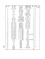
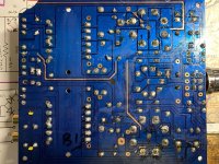
I attached a picture of the PCB and the other papers that came in the kit, along with a copy of the schematic with updated socket pin numbers.
I finally got a chance to start testing my board. First of all, I'd like to mention that I did count the EL34 sockets wrong and they are wired up correctly on the PCB. I've got pin 3 as the anode, pin 8 as the cathode, pin 5 is audio in from the preamp tube and pin 4 is connected to the B2 power supply. The power transformer that shipped with the kit has two taps on the HV side, I measured 330VAC and 262VAC with 120VAC wall current. The heater supply voltages both hovered around 7.1V. I went ahead and connected the 330V side to the board without the tubes installed in the sockets to test the B1/B2/B3 voltages and found something interesting - there were 428VDC flowing across E104/E204 for the B1 supply, 413VDC flowing across E103/E203 for the B2 supply and just over 400VDC flowing through E102/E202 for the B3 supply. I connected the 262VAC transformer tap and got the following voltages through the supply points - B1 at 357.2VDC, B2 at 356.2VDC and B3 at 354VDC.
I'm not quite sure I understand how the voltages can increase like that, as the diodes are arranged as a rectifier on the schematic and not a voltage doubler. 400-440V seems to be at the upper limit of the caps that were supplied in the kit.
I attached a picture of the PCB and the other papers that came in the kit, along with a copy of the schematic with updated socket pin numbers.
Attachments


Well it looks like my multimeter was measuring the unloaded circuit operating at the peak of my ac input under no load. If the RMS is assumed to be 40% lower than the apparent rectified voltage, I should be getting about 260VDC at the B1 pole with load going from the 330V tap on my transformer. I’ll pop the tubes in and give it a go tomorrow. Should probably be able to get some proper source voltages under load.
I added in the tubes again and went to work testing the voltages present at the power supply points. With 262VAC as my input voltage, I found:
B1 - 300VDC
B2 - 260VDC
B3 - 250VDC
I then used a USB audio card on my laptop to generate an 440Hz tone and traced the waveform with my oscilloscope. The preamp tube (6N2, similar to 12AX7) was fully functional and the signal was present and slightly amplified at the control grid of the EL34. There was an amplified signal present at the anode of the output tubes on both channels of the amplifier. I’m beginning to suspect the output transformers, as there was no resistance when measuring for continuity between the anode of my output tubes and the pole of the output transformer.
I then pulled out both power tubes and ran a tiny speaker to pin 5 of each channel to see if I could hear the test tone from the output of the preamp tube and I was able to.
Any idea on why I’m getting no audio from the output side of the transformer? There is continuity between the output jacks and the output pins of the transformer.
Last edited:
- Home
- Amplifiers
- Tubes / Valves
- Help with 6N2/EL34 tube amp kit