Hello. I am refurbishing a Gates CB500 turntable with Ashland synchronous hysteresis AC motor. The motor was running OK prior to disassembly to clean and inspect. I re-assembled the motor. Without power, the motor turns freely by hand, so there is no mechanical issue. When powered, the motor freezes (magnetically). When un-powered, the motor turns freely.
The smoothing and power capacitor have been checked and they are in good working order as they measure to infinity using my ohm meter. I get good resistance measurements across the motor terminals.
Thoughts?
Thanks in advance, Pat
The smoothing and power capacitor have been checked and they are in good working order as they measure to infinity using my ohm meter. I get good resistance measurements across the motor terminals.
Thoughts?
Thanks in advance, Pat
Were there any washers or spacers on the axis that you might have muddled up when reassembling the motor? Did you mount the stator in the right direction?
Best regards!
Best regards!
One winding or the capacitor is open-circuit? You need to measure the capacitance of the
run cap, not just that its not a resistor. If one winding is out there is no rotating magnetic field.
run cap, not just that its not a resistor. If one winding is out there is no rotating magnetic field.
Not sure what you mean by the smoothing and the power capacitor. A circuit diagram and/or photo would be helpful.
If a single capacitor (probably around 3μF) is associated with this motor, it will be in series with the start winding.
As Mark says, you should measure the value of start capacitor (if present) and compare with the value written on the capacitor. The capacitance has to be exactly as specified for the motor to run satisfactorily.
If no capacitor is in series with the motor then, as Kay says, check you have not assembled he stator upside down.
Attachments
Thanks for the responses so far.
Galu - this is a different motor than what you are showing in your picture from 2012.
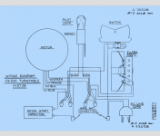
All - please see attached diagram from the user manual. It shows 2 capacitors:
1. Motor start capacitor
2. Filter assembly which has a cap + resistor
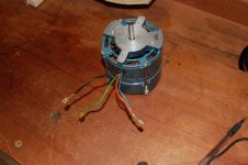
I am very confident the motor stator is in the correct direction. Washers are OK as well.
Still no luck. I can hear a small buzz/vibration when AC is powered to the motor, but that is when the motor freezes magnetically. Once the AC is shut off, the motor spins freely. I double checked the wiring and stator/rotor direction to ensure all is correct.
Galu - this is a different motor than what you are showing in your picture from 2012.
All - please see attached diagram from the user manual. It shows 2 capacitors:
1. Motor start capacitor
2. Filter assembly which has a cap + resistor
I am very confident the motor stator is in the correct direction. Washers are OK as well.
Still no luck. I can hear a small buzz/vibration when AC is powered to the motor, but that is when the motor freezes magnetically. Once the AC is shut off, the motor spins freely. I double checked the wiring and stator/rotor direction to ensure all is correct.
Attachments
Further follow-up. I have checked the capacitors and they measure 2uF (motor start) and 1uF (smoothing filter). I have tried reversing polarity of the mains and the polarity wiring to/from the caps. Still, motor freezes when AC is applied. Without AC, spins freely. Help!
Tricky one! Sounds like you're missing the rotating magnetic field in the stator. Is 2uF the value which is printed on the motor start capacitor?I measure 2uF (motor start)
Firstly is a run capacitor, not a motor start capacitor. Motor start caps are switched out of circuit by a centrifugal switch once upto speed, hence the name.
The other cap is not a smoothing cap. Its for snubbing and/or power factor correction. A smoothing cap is used with DC.
Anyway something is suppressing the rotation of the magnetic field, I'm wondering if you've got the capacitor on the correct winding, or the winding phasing right? It would be good to see the mechanical arrangement of the poles and measure the winding inductances to see how its supposed to connect up.
Another possibility is that the alignment of the motor bearings/bushings are slightly off-centre, allowing the motor to spin freely without power but causing the rotor to be pulled over against the sides when power is applied.
Take care,
Doug
Take care,
Doug
Yes Mark, there is no switchable starting capacitor in parallel with a run capacitor with this motor."Firstly is a run capacitor, not a motor start capacitor."
Suffice it to say that this motor has a single capacitor which is permanently connected in series with the auxiliary winding (also called the starting winding).
Strangely enough though, it's called a 'motor start capacitor' in the turntable manual!
If you rotate the motor spindle when power is applied, using as much force as necessary, does the effort feel like a mechanical problem, or is there only a magnetic resistance?
An important give-away is that before dis-assembly, all worked well. So it's unlikely that any of the parts all of a sudden have died at just this instance.
It heavily smells like an assembly error. I understand that your feeling is that you assembled it perfectly, that is a normal reaction.
Yet the evidence indicates otherwise.
Try to retrace your steps. Did you make pictures before-after?
Jan
It heavily smells like an assembly error. I understand that your feeling is that you assembled it perfectly, that is a normal reaction.
Yet the evidence indicates otherwise.
Try to retrace your steps. Did you make pictures before-after?
Jan
Have you measure the stators are the caps new or old, old can alter to bad when power switch on.
When i restored an TD124 to a friend it was newer used broken they sayed what i was found vas one wire how was bad connected too the wiring loom check it again.
When i restored an TD124 to a friend it was newer used broken they sayed what i was found vas one wire how was bad connected too the wiring loom check it again.
Here is an update:
1. I measured capacitance using the voltmeter. Both caps measured to spec: 1uF and 2uF. So, the caps are good.
2. Here are the measurements of the motor terminals. 2 sets of measurments. Using the continuity function on the VOM, here are the results:
black - blue: UL (unlimited)
black - orange/green: UL (unlimited)
blue - orange/green: 227 ohms
Then, measuring the resistance using the VOM:
black - blue: 665 ohms
black - orange/green: 427 ohms
blue - orange/green: 227 ohms
Not sure if this helps. Thoughts?
Pat
Further update:
1. I will retrace my assembly steps this afternoon and see if it helps. Certainly could be my issue when re-assembling.
2. The caps appear to be the original caps. Old. that said, they did measure to spec 1uF and 2uF.
3.If I rotate the motor spindle when power is applied, using as much force as necessary, it feels like a magnetic resistance keeping the motor stationary. It prevents me from turning the motor in either direction. I can feel the vibrating magnetic field. I do not get the sense that it is a mechanical interference issue.
From your resistance readings:
227Ω is the auxiliary winding (capacitor goes in series with this winding)
427Ω is the main winding (the supply voltage goes across this winding)
665Ω is the sum of the two windings
These readings look OK so the windings are intact. The fault would appear to lie with your rewiring provided, as you say, the capacitor is fine.
Attachments
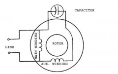
When checking your wiring to the coloured motor wires, make sure that:
Line voltage is applied across black and green/orange
Capacitor is connected across black and blue
Line voltage is applied across black and green/orange
Capacitor is connected across black and blue
- Status
- Not open for further replies.
- Home
- Source & Line
- Analogue Source
- Help wanted: motor stuck when powered