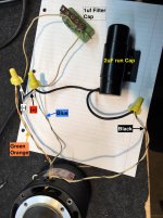
Trying to check your wiring from your photo Pat.
However, I can't see all the connections and, with my eyesight, I'm unable to differentiate the colours!
Could you sketch then post the circuit as you have assembled it?
Is the 1uF capacitor and resistor combination connected between line and the blue wire?
However, I can't see all the connections and, with my eyesight, I'm unable to differentiate the colours!
Could you sketch then post the circuit as you have assembled it?
Is the 1uF capacitor and resistor combination connected between line and the blue wire?
Last edited:
Have checked it carefully against the wiring diagram - your wiring in the photo above looks correct.
Just one probably silly thought; if the motor was reassembled incorrectly 'end for end' , and if the rotor wasn't centered in the middle of the stator windings there would be a magnetic force trying to pull the shaft against one or other end plate.
If you hold the shaft while you apply power is there any axial movement; i.e. does the shaft try to move in or out?
If you push or pull the shaft when turning it without power, does this change the rotational friction?
If you hold the shaft while you apply power is there any axial movement; i.e. does the shaft try to move in or out?
If you push or pull the shaft when turning it without power, does this change the rotational friction?
Yes, that is something I also thought of.Just one probably silly thought; if the motor was reassembled incorrectly 'end for end' , and if the rotor wasn't centered in the middle of the stator windings there would be a magnetic force trying to pull the shaft against one or other end plate.
If you hold the shaft while you apply power is there any axial movement; i.e. does the shaft try to move in or out?
If you push or pull the shaft when turning it without power, does this change the rotational friction?
I see another possibility, but my expertise in motors is not sufficient to decide whether it is likely or not: hysteresis motors rely on the remanent field created by the alternating current, but perhaps it has to be primed in some way, ie. magnetized with a strong current with the rotor held in a precise position?
It is just a hypothesis, but some types of (stepper) motors for example are destroyed just by dismantling them (opening the magnetic circuit)
I tried what Ralph recommended.
When the AC is powered: The shaft moves vertically (up) and also tilts to one side a degree or two. So, it is definitely binding somehow.
When the AC is powered: The shaft moves vertically (up) and also tilts to one side a degree or two. So, it is definitely binding somehow.
Since we have eliminated the possibility of a fault in the external wiring and componentry, it appears we have to focus on the reassembly. Next time you disassemble it, perhaps you could take some photos of the bits & pieces in the hope that someone can spot a potential directional/positional reassembly problem.The motor was running OK prior to disassembly to clean and inspect.
P.S. sq225917 posted while I prepared the above, and is thinking along the same lines as me.
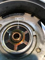
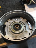
SUCCESS!!! She's running. OK, I re-assembled the bottom bushing components and I changed the order of 2 of the components. The "star" should go on top of the "small ufo disc". Then the larger UGO disc goes on top of the "star". Forgive me in advance as I do not know the correct names for these parts. Here is the proper order of assembly starting from the bottom going to the top:
1. bronze bushing
2. felt oil ring
3. small UFO disc
4. star stabilizer
5. large UFO disc
See photos. I had #3 and #4 reversed order. This allowed the bronze bushing to move freely. Once the assembly order was correct, the bronze bushing was locked into place and thus kept the motor shaft in it's place.
THANK YOU! for all who contributed on this journey. I hope this thread helps out someone else in the future. I am so happy!
Attachments

And thank-you for describing the situation, and what was needed to correct it. As you say, it may well help someone else in the future.
For what it's worth I do find the camera on my mobile phone an incredibly useful tool while dismantling and reassembling anything with more than two parts 🙂
For what it's worth I do find the camera on my mobile phone an incredibly useful tool while dismantling and reassembling anything with more than two parts 🙂
We certainly went round the houses, but all is well that ends well! 🙂
Two pluses have emerged: (a) your motor now spins again, and, (b) some knowledge of the working of turntable motors has been shared.
Two pluses have emerged: (a) your motor now spins again, and, (b) some knowledge of the working of turntable motors has been shared.
Nice thread. Nice work.
I would actually call it a phase capacitor, but what do I know😕
This is actually a fairly common occurrence in clock world. Sometimes an arbor will walk axially until it bears against it's bushing and stop the clock.
I enjoyed this thread, one of the reasons I like this forum.
Jn
Ps. In every case, I now take extensive pictures during disassembly. Every time I remove another part, click click. I will never ever say to myself "I wish I had taken fewer pictures.
Last edited:
jan.didden actually had the answer at post #13, but the rest of us were enjoying ourselves too much to pay attention! 🙂I enjoyed this thread, one of the reasons I like this forum.
I've see a lot of mislabeling as far as "motor start" (gets switched out by a centrifugal switch in the motor body) vs. "motor run" (always connected) even among pros and people who "should know better," but the REAL name ...Nice thread. Nice work.
I would actually call it a phase capacitor, but what do I know😕
Since it changes the phase of a magnetic flux, it should be called a "flux phase capacitor." 🙂
I have to comment on DIYAudio.com
Imagine 20 years ago and I had this motor problem. What was my alternatives? Toss it out, take it to a repair shop (if there even is one in my area) or get a new motor.
Yet, we have this amazing thing called the internet (BTW: I hate parts of the internet) but in case, we have a great mechanism for sharing information. And, the DIYAudio site is great. I am very thankful!
Yes, that's one of the many things that diyAudio is about, btw - we were here 20 years ago.. 🙂
I am delighted as an enthusiast of LPs that you were able to sort out the issue. 😀
Now you need to investigate powering the motor with quadrature AC in order to optimize torque, vibration and short term speed stability. (May also reduce motor heating.) Pyramid's drive thread would be a good place to start. Jaap Pees (Volken here) has tested extensively and developed single, 2 and 3 phase all analog drives commercially, but you can accomplish much the same on your own. (I use an analog single phase drive of my own design, and a modified Siemens Micromaster 3 phase VFD on my tables. One of those runs a 3 phase Aussenlauffer.)
Ah yes... a Papst Aussenlauffer... one of those 3-phase things where the outer casing is the rotor that spins, giving a "flywheel" effect.One of those runs a 3 phase Aussenlauffer.
A capacitor can be used to "trick" the three-phase motor to run on regular (two-phase) house current.
How do I know this?
Well, if the information is correct, it shows just how useful the internet can be to the uninitiated like me! 😛
Quite true, the capacitor trick, but they run a lot quieter. smoother and produce more torque on genuine 3 phase power. Regular house current is generally single phase except in some special cases, at least in North America. (I know in Germany and Belgium at least that 3 phase power is sometimes available in domestic environments.)
Apparently (internet to the rescue again!) there are still pockets of two-phase in Philadelphia and Hartford Connecticut.
Here's one of the services advertising their mastery of two-phase work. Two Phase PECO Utility Service - Philadelphia 610-853-8311.
Here's one of the services advertising their mastery of two-phase work. Two Phase PECO Utility Service - Philadelphia 610-853-8311.
- Status
- Not open for further replies.
- Home
- Source & Line
- Analogue Source
- Help wanted: motor stuck when powered