The inductor interacts with the woofer impedance. The woofer impedance is rising due to it's inductance. This can counteract the rolloff that the inductor wants to be creating.
On the other hand, the woofer is rolling off itself at some higher frequency.
Crossing precisely first order is difficult. If you don't choose to cross low, then you'll probably need a more complex circuit.
On the other hand, the woofer is rolling off itself at some higher frequency.
Crossing precisely first order is difficult. If you don't choose to cross low, then you'll probably need a more complex circuit.
At what rate? If you want a true 1st order acoustical crossover, you need both drivers to roll off at 6 dB/octave for basically a couple octaves. As AllenB said, that's easier in theory than in practice.Roll off is right at 1800 hz
According to the Madisound page for the tweeter:"by using only one series capacitor as a complete L-R 4th order crossover at 1.8k, combining acoustical and electrical slopes." So you may have what appears to be a first order crossover by the component count you're adding, but the result is likely much steeper.
thanks for getting back to me. Right now I am just trying to get values that are close. I'll post the curves when I have something useful.

Yes, I think the tweeter roll off is steeper than first order. the challenge I am having is that I am using calculations from the crossover calculator and trying initial values for the woofer. They do not seem to have any effect on the woofer rolloff - it is consistently around 6000 hz
Allen -So the impedance curve is offsetting my attempts at crossover. Is it a Zobel that I need or just a more extreme value in the inductance.
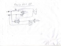
I want to cross at 1500 - 1800 hz. the calculator gives me a value of .44. Attached is the original circuit, I am guessing the 29uF caps and 15 ohm resistor are in to help with the impedance curve. However, they don't seem to make much of a difference either.
Should I increase inductance? or change the values of the Zobel. BTW, I am changing the capacitance on the Tweeter to 12 uf as that reduces the low frequency input but keeps the roll off right around 1800 hz.
If you are not going to use a simulator then it's reasonable to say that the RC impedance compensation may help, and you can keep it there while experimenting as it will make your calculations easier. The RC is going to make the inductor seem larger at some frequencies but what I'd do in your shoes it study it with and without the inductor to see where it is having it's effect.
ok, this is starting to make some sense to me. thanks! I did not check the inductors with the woofer with the RC network in place. so that would explain the responses. You are suggesting to try inductor values with the RC in place and see what happens.
Can you also give me some idea of what effect different values in the RC would have on the impedance response - for instance lower uf and resistance vs higher values?
Can you also give me some idea of what effect different values in the RC would have on the impedance response - for instance lower uf and resistance vs higher values?
There is only one optimum Zobel like set of values for R and C. Once you change them, you get more abstract with the resonance.. but that's OK.
If you reduce the resistance, you will lower the overall impedance above some frequency. If you lower the capacitance, you will raise the frequency where this happens. Changing one also has a small effect on the other (they interact).
If you reduce the resistance, you will lower the overall impedance above some frequency. If you lower the capacitance, you will raise the frequency where this happens. Changing one also has a small effect on the other (they interact).
helpful, thanks. I'll do some experimenting. I think what I would really like to do is change out the woofer but I am very restricted in size as the cabinet is epoxy cement so I can't really change that.
You could change the stuffing for a small variation in the apparent box size, or you could EQ if you need a larger variation.
Allen, that is doable, I can also plug ports if needed and go to a sealed chamber. Definitely opened the can of worms! I have decided I need to get Xsim and learn how to simulate this with a new woofer. My goal is to find one with a similar impedance, Q, and sensitivity. I am guessing impedance and sensitivity are the most important.
so I am looking at the morel TiCW 638Nd (on sale about half price). Looks like the impedance curve is fairly even and frequency looks well behaved in the frequency range I am wanting. Does this indicate it might be a fairly simple crossover circuit to get a 1st order rolloff?
I am planning on using xsim and taking measurements in the cabinet for the integration.
I am planning on using xsim and taking measurements in the cabinet for the integration.
Smooth response isn't necessary, it's just suggested for simplifying a low order crossover.
However you need to keep in mind that frequency response doesn't show you what's happening around breakup. A smooth rolloff at the top end doesn't mean it isn't breaking up. Therefore low order crossovers are often safer crossed low, but some people don't have a problem either way.
However you need to keep in mind that frequency response doesn't show you what's happening around breakup. A smooth rolloff at the top end doesn't mean it isn't breaking up. Therefore low order crossovers are often safer crossed low, but some people don't have a problem either way.
I really appreciate your responses Allen - I have wanted to just take the plunge and upgrade the woofers in these speakers since I added the Raal tweeters. So I'll have them in a week or so and take some measurements to post of the speakers in the cabinet. There is a lot of insulation in the cabinets so I have some volume to play with.
I am also going to build a external board for testing the crossover components so I don't have to keep taking the woofer off the speaker. I can use screw terminals so I can quickly change out inductors and caps. I have quite an assortment now so I should be able to hone in on something close.
I am also going to build a external board for testing the crossover components so I don't have to keep taking the woofer off the speaker. I can use screw terminals so I can quickly change out inductors and caps. I have quite an assortment now so I should be able to hone in on something close.
Ok, I am excited about this - this is the new woofer, with a .65 uH and no impedance correction (I don't have the resistors I need). The cabinet has some 1/2 " stuffing but seems to have better bass without too much. As soon as I get the resistors, I can tweak this with the impedance corrected. Then I just have to add the tweeter and adjust for SPL (impedance) as I already pretty much know the capacitor and Zobel values.


I wish you had more test equipment at hand. Some of your issues are quit daunting without it.
It is almost a shame that you've gone to a new woofer when there are solutions for the original.
Good luck and keep persevering 🙂
It is almost a shame that you've gone to a new woofer when there are solutions for the original.
Good luck and keep persevering 🙂
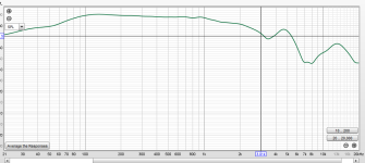
interesting post - maybe you could elucidate on the daunting issues. The new woofer has a much gentler impedance curve and a much better frequency response in the cabinet (as seen above 1/24th smoothing). I also need something a bit faster to match the impulse of the ribbon tweeter. the old woofer had lots of issues, a bad breakup region, a much harder driver to tame. So not sure why you say it is a shame.
I did say nearly a shame. Hopefully you do actually have a better woofer now.
I don't know the difference between new & old re. power, efficiency and LF extension.
I think you intend to stick with a first order (6dB) filter for the woofer, so the new
smoother and more extended driver should help your results.
My main point was that with the quite low C/O frequency of 1.8 Khz, the old woofer
could have been successfully "tamed" with the right Zobel network and a second order filter.
Re. test gear > A 'flat' sine oscillator & volt meter + the ability to measure inductance & capacitance helps so much.
Even your mic. is test gear > and I gather you're not very happy with it.
At the very start of posts, the very high top-end of your tweeter looked terrible.
I assume that is because of your mic. and not actually the tweeter (?)
Again, happy project and good luck 🙂
Ok, thanks for the clarification. I mentioned early on that I used a mic with a calibration file that I obtained online. it was terribly off. The ribbon tweeter is one of the best out there and very easy to cross with a single capacitor value. although I will also use a Zobel to flatten the impendance. That is the easy part
I do have the ability to accurately measure capacitance but not inductance. The mic I have with REW is accurate and helpful so I feel like this is a doable project.
I guess I would have liked more information in your post (as provided in your clarification) as that would have been helpful rather than seeming like a criticism. Although I have built amps and such, I am not an electrical engineer and am always learning new things and am a newbie at building crossovers. I have already learned a bunch and am hopefully going to learn a lot more from this project.
thanks for your response.
Your measurement leaves a little uncertainty. If the tweeter is as easy as you say then you may have more luck guessing at the crossover without it.. To be able to put more faith in the measurement I'd wonder about removing the room, identifying the effect of the round baffle and managing the proximity of the noise floor.and very easy to cross
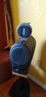
Ahh, I think I see the confusion and why mister audio responded so. This is JUST the woofer, in the cabinet no tweeter connected. I have about 1/2 inch of insulation lining the inside.
The woofer does not have a Zobel to flatten impedance just an inductor (.7 mH). I will do the impedance first per the instructions but don't have the resistors yet. I was excited because I thought that the frequency response looked pretty good with some rolloff around the point I am shooting for.
I have a very good idea of the values for the tweeter - 12uF cap with a Zobel of 6.8 ohms and .68 uF. This follows the manufactures recommendation of crossing with a single cap. The designer of the tweeter measured and gave me the specs for the Zobel. The issue I will have with the tweeter is attenuating it as I think the old woofer is more like 90 dB and the new one is 87. but I can't find good specs anywhere for the old woofer so I don' know for sure. I do know the designer had the tweeter manufacturer wind the ribbon to match the old tweeter. So at some point after I make more progress I will need help from you guys attenuating (series resistor vs l-pad)
It does raise a question. Can I get accurate measurements with just the woofer or do I need to have the complete circuitry (including the tweeter section) as I imagine everything affects everything else?

- Home
- Loudspeakers
- Multi-Way
- Help Tweaking Crossover