Here is my idea to implement current drive to my actual amp:
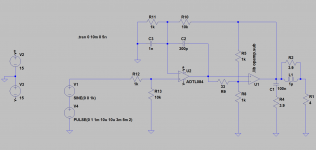
Attachment 1: my actual amp, schematic from simulation (works very well in reality!)
Attachment 2: same amp modified to current drive (not yet tested, just an idea for a simple implementation)
Attachment 3: Simulation file
any opinions so far?
Attachment 1: my actual amp, schematic from simulation (works very well in reality!)
Attachment 2: same amp modified to current drive (not yet tested, just an idea for a simple implementation)
Attachment 3: Simulation file
any opinions so far?
Attachments
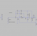
The loudspeaker inductance isn't included in the model and will reduce the phase margin and possibly cause oscillations. You could connect the bottom side of R4 to R3 to make your circuit less sensitive to loudspeaker inductance, at the expense of a lowered output impedance.
So here it is with a simulated speaker load - no signs of oscillation in this simulation. Hopefully this will also be true in reality - but i am not able to test soon, as i have a lot of other things to do first before i will find the time... 😢
Attachments

Why you need R2 and L1? These are for voltage amps. I never had them for current driveSo here it is with a simulated speaker load - no signs of oscillation in this simulation. Hopefully this will also be true in reality - but i am not able to test soon, as i have a lot of other things to do first before i will find the time... 😢
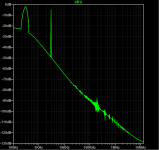
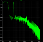
the simulated speaker impedance is a typical one to a 4inch midrange driver, so i simulated with voltage drive and current drive with dual sinewave (300Hz & 3kHz) at the typical operation range of the driver. Simulation was done with the circuits shown above. Here is the result looking at the current through the virtual voice coil
Attachment 1: spectrum voltage driven
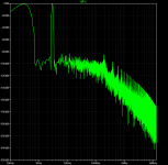
Attachment 2: spectrum current driven
Attachment 1: spectrum voltage driven
Attachment 2: spectrum current driven
Attachments
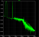
and here are the same simulations, this time a blackman harris filter was used for the spectrum, looks like the difference is very small
Attachments
I don't understand why you keep both the voltage feedback as well as the current-derived feedback.
One will lower the Zout, the other will raise it.
Jan
One will lower the Zout, the other will raise it.
Jan
Same reason as i wrote in post 186 - to have an easy implementation in an already existing circuit. Just for a first test of how it works.
Bernd
Bernd
looking closer to the spectrum at the frequencies just above the chosen sinewaves current drive shows an improvement, as far as i can see
I doubt that your simulations can be trusted. Your loudspeaker impedance model looks like it is perfectly linear, and the reason to go for current drive is that a real loudspeaker's impedance is not linear.
So can you give me a hint how to implement this? An extra current source within the Load? If yes, how to adjust the parameters?
It would be very instructive to learn what causes the impedance to depart from being linear. In other words, what changes its electrical characteristics with a varying voltage? Even material dielectric based capacitors can be said to have a non-linear impedance as dielectrics are compressed when a force acts upon them. Any charged capacitor has a force acting between its plates, and this force, compresses the dielectric changing its thickness, and I also dare say, its permittivity. The same argument can be applied to coils, chokes and semiconductor crystals. Electric fields and magnetic fields physically affect their materials slightly changing some of their properties.(Not linear meaning that current and voltage are not proportional.)
^already explained few times but just in case once more 😀
Voice coil moves. Depending on its position in magnetic gap the coil inductance varies some, or a lot, or not so much for some very good drivers. Then there are other effects, like hysteresis which is memory like effect in iron parts in driver motor, or in inductor core some loudspeakers use in crossover network. Iron as ferromagnetic material is partially magnetized in the process and this magnetic field has influence on the magnetic field in the gap the voice coil is in and thus affects movement of the cone. Heat in voice coil increases resistance, heating happens with increasing current. Perhaps many more things, I'm not too familiar with all the issues. Anyway, the more there is movement on the cone the more the parameters and impedance/current varies. Movement, excursion, is highest on low frequencies. Quick example, loud 40Hz sound could make great excursion on a woofer and modulate impedance / current for everything playing through that particular driver.
In addition to these electrical domain non-linearities there are mechanical non-linearities like stiffness of suspension, or how much of surround, as part of moving assembly in addition to "rigid" cone, moves and radiates sound, but these don't have that much effect on current and perhaps directly affect acoustic output, or some through back-EMF. Non-linearities in the motor vary impedance for amplifier voltage to convert into current, also affect how the back-EMF voltage turns to current. Current makes voice coil move and makes the problems appear in acoustic domain. When circuit impedance is increased the varying impedance of driver is reduced in relation and has less effect on current in the circuit, which also means there is less variation transmitted acoustically. Current through voice coil makes the cone move and acoustic sound. Variation here means non-linear distortion and reducing it means reducing distortion. Variation is reduced by increasing impedance in the circuit, using better drivers, utilizing less excursion.
Purifi website is good resource for quick look on the stuff, transducer non-linearities. There is probably a lot more studies on loudspeaker transducer tech around web from past about hundred years already 🙂
Last edited:

I don't know a straightforward way to do that. I think LTSpice features magnetic core models, so you could use those to model the hysteresis effects, but I never used them, and they can't model the other non-linear effects. A simple non-linear current-controlled voltage source could model static non-linearities, but none of the main non-linear effects in a loudspeaker are static.So can you give me a hint how to implement this? An extra current source within the Load? If yes, how to adjust the parameters?
Hi Marcel
But if connected in series to the load this may already show whether the amp is able to control current correctly irrespective of load. So what you proposed may not be perfectly accurate but still show whether it works in principle. Because the severity of modulation is dependant on frequency a lowpass filter might be applied in front of the non-linear voltage source.
The other possibility would be to use a "simulated inductor" for Lvc which could be modulated by the use of an analog multiplier.
Regards
Charles
- Home
- Amplifiers
- Chip Amps
- Help to understand "current drive"