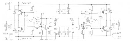
circuit is correct?
possible to replace BDX54C & BDX53C(hfe=750) WITH TIP36B & 2N3055 (hfe=20)
or not possile?
please help me to builde this project correct !!
see this link and post youer comment :
Foros de Electrónica
possible to replace BDX54C & BDX53C(hfe=750) WITH TIP36B & 2N3055 (hfe=20)
or not possile?
please help me to builde this project correct !!
Attachments
Last edited:
possible to replace BDX54C & BDX53C(hfe=750) WITH TIP36B & 2N3055 (hfe=20)
or not possile?
Yes. Possible.
TIP35/36 or TIP3055/2955 (or 2N...)...
I made quite a similar bridge with LM1875 and TIP3055/2955.
Very stable very powerfull, very nice sound. Haven't measured the THD yet, but so far looks promising.
Yes. Possible.
TIP35/36 or TIP3055/2955 (or 2N...)...
I made quite a similar bridge with LM1875 and TIP3055/2955.
Very stable very powerfull, very nice sound. Haven't measured the THD yet, but so far looks promising.
thank you for comment
my answer is possible to replace Drlingtons (BDX54C &BDX53C) WITH tip36 and 2n3055 with very low Hfe prameter and ......
?????
nice day ......
Is OK...
But i would use:
TIP35 (NPN) and TIP36 (PNP)
Or:
2N3055 (NPN) and 2N2955 (PNP)
And not lower power...
Depends on your input voltage.
You want more power, use LM1875 and close to +/-30V supply.
Or TDA2050 (max. +/- 25V).
Same circuit OK.
But i would use:
TIP35 (NPN) and TIP36 (PNP)
Or:
2N3055 (NPN) and 2N2955 (PNP)
And not lower power...
Depends on your input voltage.
You want more power, use LM1875 and close to +/-30V supply.
Or TDA2050 (max. +/- 25V).
Same circuit OK.
Last edited:
ok
but I want 100w+100w Streeo setup or 200w bridge so what is transistors ?
what is circuit revision (semiconductors - resistors - Capacitors and ....)
but I want 100w+100w Streeo setup or 200w bridge so what is transistors ?
what is circuit revision (semiconductors - resistors - Capacitors and ....)
butIs OK...
But i would use:
TIP35 (NPN) and TIP36 (PNP)
Or:
2N3055 (NPN) and 2N2955 (PNP)
And not lower power...
Depends on your input voltage.
You want more power, use LM1875 and close to +/-30V supply.
Or TDA2050 (max. +/- 25V).
Same circuit OK.
higher Hfe in Darlington Transistor = Higher Collector current=>Higher power output
(is it correct ?)
Don't guess what is necessary or how to design amplifiers unless you have more understanding. Use a straightforward design specified to do what you want and build it as designed. Play with parts and trying different components when you understand and have some experience, like after successfully building something that is known to work. (Unless you want a heap of burned parts, that is).
Something you should realise, is that you can't simply substitute industrial parts because they are all you can get. The specifications of TIP35/36 make them awful for audio and the SOA graphs say you can't get full power rating anyway. They are only 35 volt parts. If you want to get 100W/8R in class AB, you'll need to bridge two 2N3055 amplifiers, if all you can buy is these old parts. Often designs will fail because each substitute of a substitute part gets too far from the requirements of the original design. The amplifier may even work but while the original was a good design, what you may have after fitting poor substitutes, is only junk quality.
Meantime, read and learn about audio amplifier design, calculations and suitable components from the reliable articles at this site: sound.westhost.com
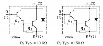
You also cannot simply substitute Darlingtons with non-Darlington transistors.
You may however make your own driver stage, similar to the internal structure of the BDX53C/BDX54C. This image shows the internal structure of the darlington. You may make this yourself, for example in place of the BDX53C, you may use a TIP31C + TIP35C together, and for the BDX54C you may use TIP32C + TIP36C.
However you will not safely get 100W with just a single pair of TIP35/TIP36 transistors. You would need at least two pairs to drive an 8 ohm speaker, at least 3 for safely driving 4 ohms.
Forget using the amplifier bridged to get more power - the quality will be poor and you will simply blow transistors.
Attachments
Don't guess what is necessary or how to design amplifiers unless you have more understanding. Use a straightforward design specified to do what you want and build it as designed. Play with parts and trying different components when you understand and have some experience, like after successfully building something that is known to work. (Unless you want a heap of burned parts, that is).
Something you should realise, is that you can't simply substitute industrial parts because they are all you can get. The specifications of TIP35/36 make them awful for audio and the SOA graphs say you can't get full power rating anyway. They are only 35 volt parts. If you want to get 100W/8R in class AB, you'll need to bridge two 2N3055 amplifiers, if all you can buy is these old parts. Often designs will fail because each substitute of a substitute part gets too far from the requirements of the original design. The amplifier may even work but while the original was a good design, what you may have after fitting poor substitutes, is only junk quality.
Meantime, read and learn about audio amplifier design, calculations and suitable components from the reliable articles at this site: sound.westhost.com
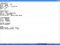
please see attached files ...
this doc file is translated by google (original spanish to englishAttachment 83330)
Iwant 100w +100w streeo or 200w mono(bridge)
my Qusetion:
1- this circuit is working with TIP36B together 2N3055 instead Drlingtons transistors (BDX54C BDX53C) ???
2- power of circuit ??? (TIP36B +2N3055)
Attachments
1- this circuit is working with TIP36B together 2N3055 instead Drlingtons transistors (BDX54C BDX53C) ???
2- power of circuit ??? (TIP36B +2N3055)
1) Yes.
But use complementary pairs...
2) 80W to 4ohm, 40W to 8ohm.
Want more power, use LM1875 and +/- 30V supply.
Same circuit OK.
Output power with LM1875 = 200w into 4ohm. 100w to 8ohm (and bridged that is).
Want even more power - forget this circuit.
Posting these articles again won't make them any more believable. As you have been advised already, the amplifier cannot even produce 100W with the power supplies or parts specified. The translated Hobby Electronics article does not promise high power at all, and only specifies +/-17V power supply for 50W music power output. That is not the same as RMS power. Please read up these definitions, often used to mislead customers.
Maybe you should also consider the size of transformer and electrolytic capacitors you will need for 400W total. You will require > 600VA for this or > 300VA for 2x 100W.
My suggestion is that since you are so focused on this basic type of hybrid amplifier, why not build it exactly as the drawings show and maybe you will be quite happy with that. It probably does operate and make sound, but not as much as you have been led to believe. Perhaps that is just as well, knowing how many fake components will be cheaply available to you.
This kind of circuit benefits from adding cascodes keeping +/- supply voltages constant and at desired value at the chip.
There is a pair plastic-transistors that will do the job well here.
MJE2955/MJE3055, wich is "clones" of the 2N3055 and MJ2955.
Good luck.
Considered this one?
YJ 2.1 LM3886+TDA7294 68W+68W+160W Amplifier board+speaker protection | eBay
MJE2955/MJE3055, wich is "clones" of the 2N3055 and MJ2955.
Good luck.
Considered this one?
YJ 2.1 LM3886+TDA7294 68W+68W+160W Amplifier board+speaker protection | eBay
Iwant to Simulation this circuit but my Proteus Simulation is not Possible Because NO model simulation for TDA2030A or LM1875 or TDA Audio Amplifier familiy in Proteus 7.71) Yes.
But use complementary pairs...
2) 80W to 4ohm, 40W to 8ohm.
Want more power, use LM1875 and +/- 30V supply.
Same circuit OK.
Output power with LM1875 = 200w into 4ohm. 100w to 8ohm (and bridged that is).
Want even more power - forget this circuit.
you can help me in simulation ?
Attachments
Simulation models
Every component requires a simulation model. The simulation software has just a selection of basic component models to get started with. These models that you will require with each new component you need, are available from the manufacturer of the component. You must download the model to your program, assuming it is in a format compatible with Proteus software.
Simulation software has manuals or inbuilt instructions that explain how to do this, if you purchase them in the proper manner. Alternatively, you could learn electronics and not depend on a computer to look up the details or do the maths.
- Status
- Not open for further replies.
- Home
- Amplifiers
- Solid State
- help to select and correct 400w TDA2030A OR 200WTDA2030