Hello, I have spent part of this summer to try to build a nice two way speaker. I have used VituixCAD2 to help with the layout of crossover. The speaker elements are Scanspeak D2010, 851300 Tweeter (oldish but not used) and Monacor SPH-165KEP. Unfortunately there is no measurefiles from ScanSpeak or Monacor, so I have used Vituix to plot. It seems to work. I posted one time earlier here at diyAudio as introduction and was recomended this forum/thread. On recommendation from @knotscott I tried to make a RC zobel to improve impedance. Crossover at 4000hz is my goal and also what ScanSpeak tells. If I raise resistans on Monacor everything falls apart in some way, but impedance can be set to 6-8 ohms. Any suggestion is welcome.
Attachments
Start the filter design from scratch and get rid of 0.47R, 39mH, RC, RLC networks.
First lower the x/o point to the lowest possible/practical.
Then shape the midwoofer LP around that.
You need to introduce the baffle step as well.
First lower the x/o point to the lowest possible/practical.
Then shape the midwoofer LP around that.
You need to introduce the baffle step as well.

Yes it seems the only way forward. Not sure what you mean with introduce the baffle step, perheps you can clarify a that? Thanks anyway.
Woofer zma file does not comply with factory specs. Repair that and check other files as well.
When you simulate the driver in a cabinet, then its SPL changes accordingly (baffle step).

When you simulate the driver in a cabinet, then its SPL changes accordingly (baffle step).
OP:
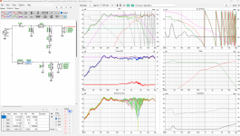
Your design should have two impedance humps, one for the woofer and one for the crossover ~ the crossover point. That it does not and your tweeter has so much output below the filter section is at least a partial clue. The other clue is that the impedance doesn't rise at all until the low pass filter kicks in. Meaning that the tweeter filter appears to be completely ineffective. Take a look at this post I made which has examples of what to expect.
Your design should have two impedance humps, one for the woofer and one for the crossover ~ the crossover point. That it does not and your tweeter has so much output below the filter section is at least a partial clue. The other clue is that the impedance doesn't rise at all until the low pass filter kicks in. Meaning that the tweeter filter appears to be completely ineffective. Take a look at this post I made which has examples of what to expect.
Thanks for your replay! I did actually a misstake when plotting (Tracing?) with VituixCAD2. It was pointed out for me in an earlier post. I just checked an sure I had missed to put the scale correct for the woofer. I start from there again and then I shall have a look at your link. Thanks anyway
Thanks! You were right, it was wrong. Thanks for observing that, it saved me a lot of headace, probably.Woofer zma file does not comply with factory specs. Repair that and check other files as well.
When you simulate the driver in a cabinet, then its SPL changes accordingly (baffle step).
View attachment 1351821
Hello @Lojzek and @eriksquires, Since you already commented on my project, perhaps if you have time can have a look at my corrections. I did correct the zma files of Monacor SPH-165 and I checked all the other files aswell. This is what I came up with, a sort of doubble Butterworth variation and a simpler one. Would you say this is right direction? I am ofcourse a beginner in this field so I need some help to get started. Thank you.
Attachments

The design presented above does not include the geometric offset distance between the centres of the tweeter and woofer diaphragms. It should be included in the simulations as it will affect the phase between the driver outputs through the crossover region.
The resistor in series with the woofer should be removed. It will dissipate a lot of power, as the woofer handles the bulk of the power contained in a typical music frequency spectrum. Looking at the filter response functions (Filter viewing panel), it is evident that the present crossover designs add about 2dB of unwanted attenuation in the 100–1000Hz frequency band. That's a lot of signal loss that will severely reduce the perceived efficiency of your two-way system.
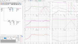
A modified crossover design is shown below. Here the centre of the woofer is mounted 160mm below the centre of the tweeter. The design listening axis is the tweeter axis. A Zobel network has been added to the woofer, which improves the overall low-pass filtering by getting rid of the 2dB trough. This system has a nominal sensitivity of about 87.5dB, compared to the 85dB sensitivity of the two earlier designs. The two drivers are both connected with positive polarity, and their outputs are in-phase at the crossover point. This makes the design a bit less sensitive to component tolerances, and the main radiating lobe is pointing directly forward. This should help maintain sound quality above and below the listening axis. The crossover frequency is about 3000Hz, which is lower than your desired 4000Hz, but may still prove suitable owing to the rapid roll-off produced by the third-order filter on the tweeter.

The resistor in series with the woofer should be removed. It will dissipate a lot of power, as the woofer handles the bulk of the power contained in a typical music frequency spectrum. Looking at the filter response functions (Filter viewing panel), it is evident that the present crossover designs add about 2dB of unwanted attenuation in the 100–1000Hz frequency band. That's a lot of signal loss that will severely reduce the perceived efficiency of your two-way system.
A modified crossover design is shown below. Here the centre of the woofer is mounted 160mm below the centre of the tweeter. The design listening axis is the tweeter axis. A Zobel network has been added to the woofer, which improves the overall low-pass filtering by getting rid of the 2dB trough. This system has a nominal sensitivity of about 87.5dB, compared to the 85dB sensitivity of the two earlier designs. The two drivers are both connected with positive polarity, and their outputs are in-phase at the crossover point. This makes the design a bit less sensitive to component tolerances, and the main radiating lobe is pointing directly forward. This should help maintain sound quality above and below the listening axis. The crossover frequency is about 3000Hz, which is lower than your desired 4000Hz, but may still prove suitable owing to the rapid roll-off produced by the third-order filter on the tweeter.
Last edited:
@Danilovitch What is the internal volume of your enclosure for the Monacor SPH-165KEP? Will you be using a vented-box low-frequency alignment?
Below is a revised design that's been adjusted to get the crossover frequency closer to the specified 4000Hz. This filter response should help protect the ScanSpeak D2010 (851300) 19-mm tweeter from excessive power inputs at lower frequencies. In any case, we have a 3rd-order filter on the tweeter, whereas ScanSpeak's testing was done using a 4kHz 2nd-order HP Butterworth filter, which is –3dB at 4kHz

Below is a revised design that's been adjusted to get the crossover frequency closer to the specified 4000Hz. This filter response should help protect the ScanSpeak D2010 (851300) 19-mm tweeter from excessive power inputs at lower frequencies. In any case, we have a 3rd-order filter on the tweeter, whereas ScanSpeak's testing was done using a 4kHz 2nd-order HP Butterworth filter, which is –3dB at 4kHz
Last edited:
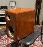
@witwald Thanks a lot for your very helpfull post. I need some time to quite understand some parts of it. Also VituixCad2 is a bit overwhelming when I try to incorporate the box size and all. But I will manage. I few answers at this stage: box size W18cm H32cm D31cm so almost 18 liter. Inner shelf of mdf 19mm (ala CSS Criton 1TDX). In general I wanted to try a sort of scaled up version of my ProAc Response 1s, as a model I mean. So the layout of the elements are similar, with tweeter ofset of Bas/mid element. The vent port is per size and rec. by Monacor 70mm in diameter and at the moment 165mm long, placed at the upper part of cabinett offset of tweeter. Also this inspired by ProAcs.
Thanks for your support and your suggestions of a better crossover. As soon as I can I will try it out.
Thanks for your support and your suggestions of a better crossover. As soon as I can I will try it out.
Attachments
If we assume that the walls of the enclosure are at least 1.9cm thick, the net enclosure volume after subtracting the shelf and the port is going to be something like:
((18-3.8)x(32-3.8)x(31-3.8)-(18-3.8)x(31-3.8)x1.9-πx7^2/4x16.5)/1000 = 9.5 litres.
The net volume of 9.5 litres is much smaller that 18 litres. If the free-air resonance frequency of the Monacor SPH-165KEP is really Fs = 30Hz as per the datasheet, it will result in a very long port length (much longer than 165mm) if a 70mm port is used.
A workable design for a 9.5-litre vented enclosure is simulated using VituixCAD, and the results are shown below. This is for 10W input (re 8 ohms), and produces moderately high vent air velocity (18.4m/s @ 23.8Hz). I allowed for a small 1-dB peak in the response at about 100Hz to keep the vent length at 14.7cm for a 4.0cm diameter. The vent tuning frequency is 44.1Hz for this design, and its −3dB point is F3 = 57.4Hz.
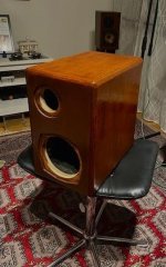
I guess this is more or less in keeping with the ProAc Tablette. It might be worth placing the port on the rear of the cabinet to help make any port chuffing noises less noticeable.

If an enclosure with 18 litres of internal volume was available, then the following frequency response could be expected. The port would be 13.4cm long and 5.0cm in diameter, tuned to 40.0Hz. The −3dB point is F3 = 42.4Hz, which is quite low.

((18-3.8)x(32-3.8)x(31-3.8)-(18-3.8)x(31-3.8)x1.9-πx7^2/4x16.5)/1000 = 9.5 litres.
The net volume of 9.5 litres is much smaller that 18 litres. If the free-air resonance frequency of the Monacor SPH-165KEP is really Fs = 30Hz as per the datasheet, it will result in a very long port length (much longer than 165mm) if a 70mm port is used.
A workable design for a 9.5-litre vented enclosure is simulated using VituixCAD, and the results are shown below. This is for 10W input (re 8 ohms), and produces moderately high vent air velocity (18.4m/s @ 23.8Hz). I allowed for a small 1-dB peak in the response at about 100Hz to keep the vent length at 14.7cm for a 4.0cm diameter. The vent tuning frequency is 44.1Hz for this design, and its −3dB point is F3 = 57.4Hz.
I guess this is more or less in keeping with the ProAc Tablette. It might be worth placing the port on the rear of the cabinet to help make any port chuffing noises less noticeable.
If an enclosure with 18 litres of internal volume was available, then the following frequency response could be expected. The port would be 13.4cm long and 5.0cm in diameter, tuned to 40.0Hz. The −3dB point is F3 = 42.4Hz, which is quite low.
Last edited:
Well, I'm embarassed you used my name in the same sentence as @Lojzek , i don't think I deserve the comparison. Still, your impedance charts don't make sense to me at all. I'm afraid I can't download your files, but show me the impedance of each section independently, and compare to the charts on my blog: https://speakermakersjourney.blogspot.com/2016/12/crossover-basics-impedance.html
Hi @witwald, thanks! I am so sorry I forgott to mention that I was writing the inside dimensions. I was in a hurry this morning. The walls are 19mm mdf + 5mm of leaftree so 24mm in total. But thanks for the pictures that looks very intresting on how to execute Vituixcad2. I shall have a look at this in the evening.If we assume that the walls of the enclosure are at least 1.9cm thick, the net enclosure volume after subtracting the shelf and the port is going to be something like:
((18-3.8)x(32-3.8)x(31-3.8)-(18-3.8)x(31-3.8)x1.9-πx7^2/4x16.5)/1000 = 9.5 litres.
The net volume of 9.5 litres is much smaller that 18 litres. If the free-air resonance frequency of the Monacor SPH-165KEP is really Fs = 30Hz as per the datasheet, it will result in a very long port length (much longer than 165mm) if a 70mm port is used.
A workable design for a 9.5-litre vented enclosure is simulated using VituixCAD, and the results are shown below. This is for 10W input (re 8 ohms), and produces moderately high vent air velocity (18.4m/s @ 23.8Hz). I allowed for a small 1-dB peak in the response at about 100Hz to keep the vent length at 14.7cm for a 4.0cm diameter. The vent tuning frequency is 44.1Hz for this design, and its −3dB point is F3 = 57.4Hz.
I guess this is more or less in keeping with the ProAc Tablette. It might be worth placing the port on the rear of the cabinet to help make any port chuffing noises less noticeable.
View attachment 1354627
If an enclosure with 18 litres of internal volume was available, then the following frequency response could be expected. The port would be 13.4cm long and 5.0cm in diameter, tuned to 40.0Hz. The −3dB point is F3 = 42.4Hz, which is quite low.
View attachment 1354630
That's great news that they were the internal dimensions! The internal volume comes to around 15.9 litres, which seems plenty for the Monacor SPH-165KEP based on the Thiele–Small parameters in the datasheet. With a Dv = 7.0cm vent diameter, the VituixCAD estimates the vent length to be Lv = 35.1cm, which is quite long. The resulting bass response curve for a vent tuning frequency of Fb = 40.0Hz is shown below. The −3dB point is F3 = 44.3Hz.

If we swap to a vent diameter of Dv = 5.0cm, the estimated vent length drops considerably to Lv = 16.0cm. With this configuration, the driver's Xmax is reached with 18W (re 8 ohms) of input power. At the same time, the maximum air velocity in the vent hovers around the lower of VituixCAD's guidelines (turbulence warning).
By the way, the following VituixCAD table shows the set of Thiele–Small parameters that I took from the woofer's datasheet.
Here are impedance plots of the woofer and tweeter with their low-pass and high-pass filters in place, together with the resulting overall system impedance curve.... but show me the impedance of each section independently, and compare to the charts on my blog: https://speakermakersjourney.blogspot.com/2016/12/crossover-basics-impedance.html
The hump at 5k and 30Hz look typical, the decrease in the bass section between 500 and 2.5kHz are really not. Let me download your files and see if I can do something with them.
So, taking a closer look at your files, your amplitude problem is your impedance problem. You are getting excessive output in the woofer around 2 kHz. Flatten it and reduce your tweeter output. Your impedance problem should rectify itself. Examine the transfer function (graph labelled Filter) for the woofer. The low pass slope is OK, but before that you have a hump that does not need to be there at all. Double check your woofer + zobel aren't the issue. With just the woofer and zobel you should have a flat impedance curve, not a dipping one.
Last edited:
Here are the VituixCAD files. The impedance curve for the woofer was re-digitized, as the original had 1-ohm-ish impedances at 5Hz (outside the frequency band of interest, but not quite representative). The decrease in the bass section is due to the need for the filter to slightly EQ the woofer response, by about 1.5dB, to get it relatively flat. The minimum impedance doesn't drop below 4.9 ohms, so I don't think it is a problem. In any case, the frequency region where the minimum occurs is somewhere that music doesn't have as much energy as in the low frequencies.The hump at 5k and 30Hz look typical, the decrease in the bass section between 500 and 2.5kHz are really not. Let me download your files and see if I can do something with them.
The relevant VituixCAD project and driver data files are attached.
Attachments
I'm not entirely sure that we should try and reduce the output of the woofer to reduce the hump in its filter's transfer function. That will reduce the sensitivity of the system in the midrange area, which is potentially more undesirable.
Here the raw woofer response has a bit of a downward tilt. A little bit of filtering EQ is not unusual when dealing with driver natural frequency response functions.
Below is a plot of the woofer impedance curve with the Zobel network in place. It has flattened the rising impedance of the woofer quite well. The impedance is about 7 ohms between 200Hz and 2000Hz, and then log-linearly rises to 9 ohms at 20kHz.
Last edited:
- Home
- Loudspeakers
- Multi-Way
- Help to raise impedance in a 2way system