Thank you Edmond
I gave up on that circuit even do I invested a lot of time and energy.
I think I will convert your circuit. You wrote on the other forum that works and tested OK.🙂
I do started the layout.
I will take a look one more time the orig Cordell circuit.
I do not understand why he used on every power mosfet a Zobel like solution.😕
Can I use your circuit for my Toshiba devices?
Greetings Gabor
Attachments
You have many of those transistors. Why not just send a few to Ostripper or others so they can provide you with a tested circuit.
Or find the model for those transistors and post the circuit topology you are interested with. Hopefully many will "design" it in simulation but of course the first option is better.
Or find the model for those transistors and post the circuit topology you are interested with. Hopefully many will "design" it in simulation but of course the first option is better.
Hi Gabor,
Do you mean the auto-bias OPS as depicted above? That circuit has never been built. Perhaps you confuses it with the Super-Tis front-end.
Cheers, E.
Thank you Edmond
I gave up on that circuit even do I invested a lot of time and energy.
I think I will convert your circuit. You wrote on the other forum that works and tested OK.🙂
Do you mean the auto-bias OPS as depicted above? That circuit has never been built. Perhaps you confuses it with the Super-Tis front-end.
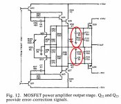
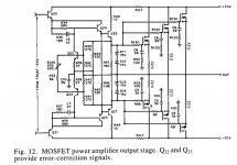
Do you mean C8, C9 etc? Probably you will need it for each MOSFET and put them as close as possible to the gates. According to Bob this stuff prevents HF oscillations.I do started the layout.
I will take a look one more time the orig Cordell circuit.
I do not understand why he used on every power mosfet a Zobel like solution.😕
Yes, of course. 2SJ200/2SK1529 are the same as 2SJ201/2SK1530 except Vds max: 180V vs 200V. But I wouldn't recommend this circuit, as it has not yet been built and tested.Can I use your circuit for my Toshiba devices?
Greetings Gabor
Cheers, E.
Attachments
Thank you Edmond🙂
I taught your circuit was built and tested in real life, probably I misunderstood something.
OK I do take your advise and go with the original Cordell all do I'm not sure that was built in real life or not.
To use 3 pair output for the higher power I needed to do some minor mod. can you take a look these is correct how I drawn.
Each mosfet will get a 39pF and 100R because of that I needed to switch location of the diodes - drain resistors and C8 R52
Thank you very much one more time.
Jay I did posted at OS thread a couple option before (they do not interested on these expensive Toshiba devices)
I had the feeling I just pollute his thread with my Toshiba devices.
I do not have enough to send OS 2X3 matched pair and to have for myself also. Not to talk about in case something goes wrong at power up (it happened only once under the 25 years- I blew😱 up the amplifier at power up) I have to keep some spare.
They are to busy with the new IPS at these moment
Otherwise it would be a good idea.
Greetings Gabor
Attachments
Hi
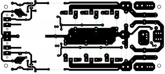
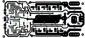
Just finished the layout based on the Cordell circuit with some minor mods.
C8,C9 hopefully is pF value not nF (actually I'm not sure about that)
The 100R resistors are SMD type.
It does has the option to use of the regular Zobel N if needed.
Also I added 2.5uH inductor with a 10R resistor (optional)
I do have to go over Cordele's file to get better understanding on the function of these amp.🙂
I needed to mode the front end so I can hock it up with the mentioned IPS.
Can someone take a look if the layout is correct also the added mode to.😀
Thank you guys
Greetings G
Attachments
Hi
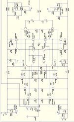
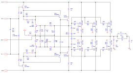
I redraw the schematic because hard to see the original.
Edmond, Jason and others would you please let me know your opinion if these correct!
I did some minor mode, otherwise I can not hock up with the IPS I would love to.
If these correct I will go on and etch the PC boards.
Thank you
Greetings Gabor
Attachments
Last edited:
- Status
- Not open for further replies.
- Home
- Amplifiers
- Solid State
- Help to convert these Lat-Fet amp to Toshhiba mosfet