Back to Square one
I considered all the advise I got, I think the best for start to do build first the one Mr.Cordell shared with us with Lat-fet.
In that case I will have a base so after any modification to compare it.
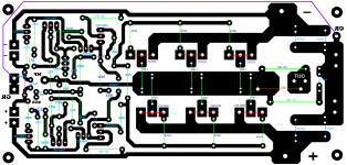
If someone interested on these amplifier here is the layout for the circuit at first post.
Please go over and double check it, look for errors in case, IT WAS NOT TESTED yet!
I think the idea Alex came up will be a good point to start.🙂
Also metallicus69 last option worth a try.🙂
Now I need to rework the layout after I apply the Alex advise..
Greetings
I considered all the advise I got, I think the best for start to do build first the one Mr.Cordell shared with us with Lat-fet.
In that case I will have a base so after any modification to compare it.
If someone interested on these amplifier here is the layout for the circuit at first post.
Please go over and double check it, look for errors in case, IT WAS NOT TESTED yet!
I think the idea Alex came up will be a good point to start.🙂
Also metallicus69 last option worth a try.🙂
Now I need to rework the layout after I apply the Alex advise..
Greetings
Attachments
I came up with a small modification but only will stay if you guys think is a good idea.
I added four diode with underlined with red.
Alex and other DIY-ers please let me know your opinion.🙂
Thank you
Greetings Gabor
Yes you right I put the wrong diode to the wrong place
I added four diode with underlined with red.
Alex and other DIY-ers please let me know your opinion.🙂
Thank you
Greetings Gabor
Yes you right I put the wrong diode to the wrong place
Last edited:
D21 and D14 are the wrong way around.
Flip them both.
Thank you for pointing it out🙂
I corrected now.
Any opinion on those diodes
Greetings gabor
Attachments
Any opinion on those diodes
Greetings gabor
They are there to protect the mosfet gates.
I use ALF16N16W and ALF16P16W lateral mosfets and they have no gate protection diodes so you have to add a zener diode externally to protect the gate.
Also with lateral mosfets you can choose the zener voltage so it sets a current limit on the mosfets.
ALFET recommend a 12V zener to limit the current to about 11 amps. The ALF16N16W has a 1 ohm resistance across the drain and source.
So 12 volts divided by 1R gives about 11-12 amps current limiting.
Here is a good article on lateral mosfets:
http://products.semelab-tt.com/pdf/ApplicationNoteAlfet.pdf
Last edited:
Lateral Mosfets
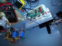
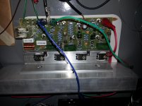
Why work so hard to convert to vertical mosfets when newer lateral mosfets are coming down the pipe. As Alfets are mentioned and I fired up tonight one of seven amps built for a home theater project. Double D single die mosfets replaced the 1058/162 laterals. Setting here listening to sweet accurate music. No harshness as with so many BJT's at high volume. Built plenty of them. Pics for fun🙂 John
Why work so hard to convert to vertical mosfets when newer lateral mosfets are coming down the pipe. As Alfets are mentioned and I fired up tonight one of seven amps built for a home theater project. Double D single die mosfets replaced the 1058/162 laterals. Setting here listening to sweet accurate music. No harshness as with so many BJT's at high volume. Built plenty of them. Pics for fun🙂 John
Attachments
Built several Lat-fet amplifier, some famous circuit among them.
I have some problem at bass region, a bit shy at bass area, these not only my opinion also read similar feedback from other peoples to.
You may disagree with these, but these is my opinion only.
Again I built several lat-fet amplifier, I hove some of these Toshiba in my toolbox why no to give try.
Greetings
Sorry, too many devices in work. They are
class D lateral mossfets. John
I do have some of those high power devices.
Hi
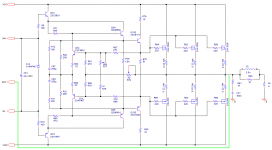
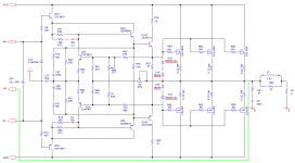
Just finished the layout for the amplifier the way Alex advised🙂
May be not 100% the same way, at least to me it is very close
Alex can you confirm the circuit how I converted is correct please so I can go on and fabricate the PC boards.😕
I want to be sure at least operational and I didn't misunderstood your advise.
The feedback I marked because I want to use some IS like these one.
If no need for I can just disconnect it.
Thank you guys
Greetings
Attachments

Hi, Gabor! Shortly :
1. R12|C47 and R11 C46 are optional. It may be need in parallel with R71|R72 too.
This is a frequency compensation of correction feedback loop.
2. Gate resistors of power MOSFETs , i suppose, ~ 51E.
3. I don`t see DC servo loop(?)
4. R79|R80 may be eliminated.
And process of turning to minimal distortion:
1 Set R77 to maximal, turn on the divise and control bias current by voltage on source resistors, then set output signal (for example 1kHz) 75% of max unclipped amplitude with connected load (4-8 Om ?).
2 Slowly lower value of R77 to find a sweet spot in minimal THD, then find more lower THD with fine turning of R74.
All this do without overall feedback. My greatest approach, for these Toshibas, is ~ 0.006% THD.
Nice front end, meanwhile. I was created something like this when was young, but more complicated (with current mirror linearizion also based on error correction principle and advanced cascode in first stage too)
Hi Alex
Thank you
I made those changes you advised, also I sent you a PM.🙂
Previously post I posted the wrong circuit (was not included the 4PC diodes so you couldn't give advise on that.
The R79, R80 will be removed.
For R73, R74 andC3, C4 I used the same value originally was there, is those are acceptable.
About the DC servo ?????
I will send a PM with my e-mail address.🙂
Greetings G
Attachments

Last edited:
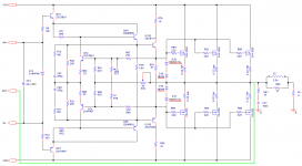
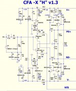
The latest circuit
Hi
I big thank you for all of you who helped me to arrive here!
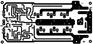
These two resistors R79|R80 I leave it for now.
I will test it in real life if I can hear any difference, otherwise I will use a jumper.
More advise always welcome🙂
Greetings
Hi
I big thank you for all of you who helped me to arrive here!
These two resistors R79|R80 I leave it for now.
I will test it in real life if I can hear any difference, otherwise I will use a jumper.
More advise always welcome🙂
Greetings
Attachments
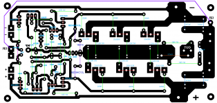
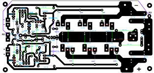
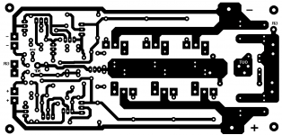
These is the latest layout in case someone interested on these amplifier
I hope the circuit is correct
I will re check the layout for errors one more time, to me it look like correct.
More worried about the schematic after all that modification if it will perform well or I will waste my time and energy and some fund. 🙂😱Advise opinion still welcome.🙂
Greetings gabor
I hope the circuit is correct
I will re check the layout for errors one more time, to me it look like correct.
More worried about the schematic after all that modification if it will perform well or I will waste my time and energy and some fund. 🙂😱Advise opinion still welcome.🙂
Greetings gabor
Attachments
Hi
Very likely these project will be a faller unfortunately.🙄
Somebody made some sim and the result way of. Here is the sim result by his words
Hi Gabor,
I did a quick and dirty sim of the Alex style compensation and the result was disastrous. Perhaps I'm overlooking something. So do you have a link to his original schematic?
Best, Edmond.
So bad because I invested a lot of time and energy. Specially into the layout.
What can I do now
Greetings Gabor
Hi
[..]
Hi Gabor,
I did a quick and dirty sim of the Alex style compensation and the result was disastrous. Perhaps I'm overlooking something. So do you have a link to his original schematic?
Best, Edmond.
To make sure the compensation was wrong, I did one more simulation and again the result was disastrous. For someone who claims this, rather embarrassing I would say, the more so as on several occasions Bod Cordell has explains how his compensation works. That should have made clear it's hard to improve, let alone to spoil it.
Well, as I said before, stick to Bob's design and for more power add some more output devices, i.e. the vertical MOSFETs you already have.So bad because I invested a lot of time and energy. Specially into the layout.
What can I do now
Greetings Gabor
Cheers, E.
- Status
- Not open for further replies.
- Home
- Amplifiers
- Solid State
- Help to convert these Lat-Fet amp to Toshhiba mosfet