Hi
I would like to get some help to convert these Lateral mosfet amplifier to Toshiba 2SK1529 & 2SJ200 (vertical type)
I do have at least +20 pair of that Toshiba mosfet. I built several Lat-fet amplifier I would love try out these circuit with those Toshiba devices.
At least close to these circuit with the req. mod.
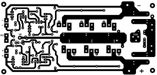
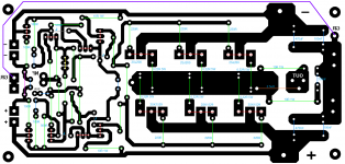
I have the layout for these OS
Thanks for your help and advise
Greetings
I would like to get some help to convert these Lateral mosfet amplifier to Toshiba 2SK1529 & 2SJ200 (vertical type)
I do have at least +20 pair of that Toshiba mosfet. I built several Lat-fet amplifier
I would love try out these circuit with those Toshiba devices.At least close to these circuit with the req. mod.
I have the layout for these OS
Thanks for your help and advise
Greetings
Attachments
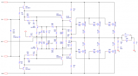
As far as I know there is not much difference in their caracteristics of the originals (SSK 1058-2SJ 162) and the Toshiba ones. Higher Id, higher Uds, more Pd, and slightly different trensfer caracteristics. And yes, different pin layout.
If you replace R70 (or R89) with a 1k trimpot you will be able to set Io with the Toshiba devices. Their Cgs capacitance is a bit higher too, but with the kind of drive on your schematic this should be no problem. Also the 470 ohm gate stoppers seem to be a bit much for those devices ,try 150-220 ohms instead.
If you replace R70 (or R89) with a 1k trimpot you will be able to set Io with the Toshiba devices. Their Cgs capacitance is a bit higher too, but with the kind of drive on your schematic this should be no problem. Also the 470 ohm gate stoppers seem to be a bit much for those devices ,try 150-220 ohms instead.
Last edited:
Thank you very much
The main issue here one is lateral the other Toshiba is vertical mosfet
One has negative tempco the other opposite.
If I do not take care about that it will be thermal issue and probably other problems to.
I totally agree your advise just not sure that will take care all, that mode will do the trick.
Greetings Gabor
You can use an active Vbe multiplier then in place of R70 and 89, with its transistor mounted to the FET-s heatsink for thermal compensation, as with a standard BJT output stage.
Vgs...I don't think so.
Check the attached PDF in this post. I did some trials with a 1530/201 output stage to achieve perfect thermal stability.
http://www.diyaudio.com/forums/soli...n-subwoofer-wideband-duty-13.html#post3382545
Check the attached PDF in this post. I did some trials with a 1530/201 output stage to achieve perfect thermal stability.
http://www.diyaudio.com/forums/soli...n-subwoofer-wideband-duty-13.html#post3382545
What is being Multiplied is the Base/ Emitter voltage of a BJT not the VGS of a FET ?
Yes a BJT is fine for the job I have used it in numerous designs.
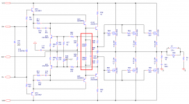
I made some progress but very likely need some improvement.
Please guys take a look if these idea will, it is correct if not please land me a hand.. Or some more advise🙂
Some question what do I do with the original trimmer- just replace it with a resistor if yes what value do I pick.
Thanks
Greetings
Please guys take a look if these idea will, it is correct if not please land me a hand.. Or some more advise🙂
Some question what do I do with the original trimmer- just replace it with a resistor if yes what value do I pick.
Thanks
Greetings
Attachments

Before I start to mode the layout it would be great if I could get more comment, feedback on the latest circuit with the VBE.
I do have the feeling that one of that trimmer can be removed or be replaced by a resister.
Your advise is welcome, yes I'm open to learn..🙂
Greetings
I do have the feeling that one of that trimmer can be removed or be replaced by a resister.
Your advise is welcome, yes I'm open to learn..🙂
Greetings
Attachments
Yes a BJT is fine for the job I have used it in numerous designs.

The Vbe multiplier circuit (BJT) can include resistors to adjust Gm vs temperature to closer match the mosfets. A little trial and error adjustment might be needed to get thermal tracking spot on. However, due to the generally
 lower Gm of mosfets, the thermal monitoring can be more forgiving than for BJT output devices, but is still necessary with verticals which are bias in class AB. 😎
Verticals can be problematic with regard to HF oscillation bursts under certain normal operating conditions. It would not hurt to include a gate to drain Zobel filter, just some small SMDs, onto the PCB layout. Metal film resistor ~150R and COG type capacitor ~47pf. It might allow for the use of a smaller gate stopper yet still maintain unconditional stability.😉
Last edited:
It would not hurt to include a gate to drain Zobel filter, just some small SMDs, onto the PCB layout. Metal film resistor ~150R and COG type capacitor ~47pf. It might allow for the use of a smaller gate stopper yet still maintain unconditional stability.😉
Forgive me I do not understand 100% your advise.
A sketch definitely would be a great help or a example to understand it what you are referring.
Please in case you know where I can read more about or study it let me know the site.
Thank you very much.
Greetings
Also based on your opinion if I would build it how it is now these would work.
Thank you!🙂
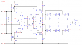
Almost ready with the layout🙂
The VBE need to be added after double check and I can etch the PC boards.
I do stopped because I'm still not sure that VBE correct, or even if it would work.
Sometimes think just works or can be acceptable but that not the main reason we DIY.😀
It would be great if I can get more feedback before I etch the PC boards.
Thank you guys in advance
Greetings Gabor
Attachments
You error correction circuit looks to be Bob Cordell's implementation. I have little experience with EC circuits, but my understanding is that the EC amplifier also provides the spreading voltage so there is no specific requirement to use a separate VBE multiplier. That of course is as applied to mor typical verticals devices.
That said, you have arranged the driver emitter resistors to reduce gate drive and rightly so since your Toshiba devices have a lower threshold voltage. I see no reason to not expect the design to function, just be prepared to adjust some resistor values in real life.
Build and test carefully. The Toshiba devices are verticals but have some interesting characteristics that give them some features more like laterals and BJTs. I have no specific advice or direct experience to offer. My (and Valery's) SlewMaster conversion to the IRFPs did not use error correction and simply required tailoring the VBE to accommodate them, as such it was pretty straight forward.
- Status
- Not open for further replies.
- Home
- Amplifiers
- Solid State
- Help to convert these Lat-Fet amp to Toshhiba mosfet