Those base and emitter voltages are to close for comfort.
R105... well its easy to tag one across and see what happens... its unlikely I think.
Let me just dig out a germanium device and see how it reads on a DVM.
R105... well its easy to tag one across and see what happens... its unlikely I think.
Let me just dig out a germanium device and see how it reads on a DVM.
So an OC71 reads around 800 ohms B to E and B to C when forward biased. That means black (negative) lead on the base. With the red lead on the base it reads 'open' on a 2k range on my DVM.
On the diode range it reads about 12 which actually means 12 millivolts (there is just so much leakage with germanium). A silicon device would be in the 600's on the diode range. Again meter lead polarity is important.
Based on what you say the transistor is looking suspect.
If you remove the transistor fully then the collector volts (where it was anyway) should come up to -18 and the base to the marked value of 1.35 volts. The emitter point would be zero.
Ok!
I removed the emitter and collector leads and measured the following:
Where collector was on the terminal strip now reads -17.9v
Base= -1.1 (still connected to terminal strip)
Emitter= -1.1
Collector= -1.1
Powered off amp and set meter to ohms with negative on base:
B -> E = 19.7ohms
B -> C = 62.4ohms
Positive on base:
B -> E = 19.7ohms
B -> E = 64ohms
Hopefully I did that right, lol.
Erm... it sounds like something is amiss.
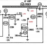
Look at the diagram. With the transistor removed (or at least two of the three leads isolated) we must see the following and these are all voltage readings...
The emitter must be 0.00V because it is only tied to ground via a 1k resistor.
The collector must read the same as the supply voltage because that is tied to the supply rail by the 6800 ohm resistor.
The base sees a voltage determined by the divider consisting of the 220k and the 18k. If the supply is -19 volts then the voltage at the base is (quick calculation):
I=V/R and so I = -19(220k+18k) which is -0.0798 milliamps.
Voltage across the 18k is V=I*R which is -0.0798E-3 * 18000 which is -1.43 V.
So the base point should have around -1.43 V present. The exact value depends on the exact supply voltage and the exact resistor values but that is unimportant. Around -1.4V is the expected result.
Attachments
lol... the only thing that is amiss is my ability to follow directions...
You are correct. Base terminal is -1.1v, collector terminal is -18v, and emetter terminal is 0v.
Sorry for not getting that right.
You are correct. Base terminal is -1.1v, collector terminal is -18v, and emetter terminal is 0v.
Sorry for not getting that right.
That is looking at face value like a failed transistor then. Do you know the part or device number of it?
-1.1 volt on the base is a wee bit low sounding but is does depend on the exact resistance values in that bias network. -18 volts should see around 1.36 volts.
It is probably unrelated but worthy of looking at at some point. Either the 220k is high, the 18k low, or the cap C21 is leaky... thinking aloud now... the leakage of a 25uF might be enough to slightly alter the figures anyway.
So at this point I think you have to stick another transistor in there. Do you have any general purpose small signal types, even if they are silicon?
We disconnected one leg of C21 (Which is new) during testing...
I don't have much for transistors. I have a large assortment of misc junk (mostly resistors) from a friend that I mess around with when working on LED's. I found some NPN transistors in the mess, but I'd rather order the best possible replacement.
I was digging around online yesterday to try and find suitable replacements, and I found 2N109. Just have to try and sort through specs to find a modern replacement that matches the specs.
Any recommendations?
The 2N109 is a germanium... if that is what is fitted then its a case of seeing what is available.
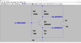
The circuit should also be suitable for a silicon device with only a small change to the bias network. That 220k would need lowering to bias the transistor to around -9 volt on the collector. Somewhere in the 120 to 150k region I would guess.
Any small signal type like a 2N5401 or a BC557 or BC558 should work here.
---------------------
With C21 disconnected and the transistor removed we have simple voltage divider consisting of the 220k and 18k in series across the -18 volt supply. The theory on that is bullet proof. If the resistors are as marked then the voltage would be -1.36 volts with an -18 volt supply. One further source of measurement error is the loading of your meter which would pull the voltage down a little. Lets not get hung up on that at this point 🙂 Its a curiosity rather than a problem at this moment.

Oh wow, ok!
I will go with what you recommend. I'm only looking for the same audio performance, or better than original, without having to go crazy with modifications.
If you are able to provide a BOM, then I can try stopping at my local electronics supply shop today sometime to pick it up (If they have stock)
Thanks so much, I really appreciate the time your taking to help a newbie get this old console back to working condition.
Do you need a full wiring diagram for reference?
That stage is all that was needed 🙂 as it is self contained.
You will not do any harm in trying anything you have at hand. The transistor type isn't critical but check the pin outs with reference to a data sheet before fitting. If you have any scrap equipment then have a look at what is in there. 2SA prefix (in the JIS or Japanese numbering system) are PNP types. Anything small signal should work here.
The only other parts you might get are a 150k and lets say a 120k resistor. 0.25 watt is fine here as is 5% tolerance or better.
While I remember... it is odd for this transistor to fail following just a recap... if that is what happened... or was the recap to fix the fault.
For the former, one thought was whether your soldering iron had some leakage current and whether you had the amp plugged in while you were soldering.... just a thought.
I'll have to leave it for now 🙂
They should work all being well 🙂
The -9 volts on the collector is a voltage to aim for with the biasing. With it set to approx half the supply the transistor can swing equal above and below that point. If the bias point is off (to high or to low) then the maximum voltage swing is limited and the stage would clip prematurely on either top or bottom of the peaks.
The -9 volts on the collector is a voltage to aim for with the biasing. With it set to approx half the supply the transistor can swing equal above and below that point. If the bias point is off (to high or to low) then the maximum voltage swing is limited and the stage would clip prematurely on either top or bottom of the peaks.
 I'll look in tomorrow.
I hate it when people don't report on the final outcome......
I am happy to report success! Replacing the transistor and resistor solved the problem with the right channel.
I still have no idea how it failed. I was working on replacing the capacitors on another area of the amp, which is about 8" horizontally away, (left channel) so either a blob of solder went flying and shorted it out, or it was time for it to die.
Either way, i changed out 4 more capacitors and it still plays from both channels.
My final question, is should i replace the left channel transistor and resistor, or should i leave it?
Thankyou so much for your time and patience. I very much appreciate it!
I would change them out, simply because both channels will match, and also there might just not be enough life left in the old ones.
Maybe the newer capacitors will give a better sound through a new transistor.
Maybe the newer capacitors will give a better sound through a new transistor.
Last edited:
- Home
- Amplifiers
- Solid State
- Help to confirm capacitor polarity