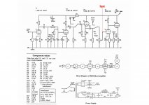
I built Jan Lodstrom's reMUS phono-line preamp from a Sound Practices article at an old and it just won't work. I get no sound out of it! 🙁
I have checked all the components and connections and everything is kosher and the valves are all either new or NOS tested by the retailer. I have attached the schematic and components list to this message.
I decided to try and figure out what stage of the pre-amp is problematic. I have established that the line stage is not working. (I have not checked phono yet so not sure, but let's fix this for the time being and worry about the rest later.) I did this by running my ipod straight into the point that I have labelled "Input" on the schematic.
Could anyone please suggest where I could start looking for problems? My understanding of electronics is limited and this project and the research around it in part serves the purpose of learning so that I make more ambitious things in the future, so please bear with my ignorance.
Some facts that may or may not be significant:
1. Instead of the suggested B+ supply, I am using an RCRCRC filter after bridge. I am getting ~270-280 V DC out of it.
2. My power transformer is a bit too powerful for my purposes, so I had to kill a lot of voltage with the filter. To get to he 270-280V there was a fair deal of trial and error with different resistance values. This meant that I had to run the pre-amp at voltages up to 370 V a few times, all of which for less than one minute. Is there any way I could have damaged anything by doing this?
3. Initially, I had forgotten the C11 capacitor and ran this a few times without it. Again, could I have damaged anything as a result of this?
4. Instead of the suggested 6V supply for the heaters I am using a regulated supply designed by Wavebourne. I am getting 12.85 V DC out of that. (I have of course wired the heaters accordingly.)
5. Although the schematic calls for 3 ECC83s and two ECC82s, I have used (in a V1-V5 order) two ECC83s followed by one ECC81 before the volume pot, followed by an ECC82 at the first stage of the line and an ECC81 at the end. I did this following the suggestions in the article accompanying the schematic, which read:
"The preamp uses five tubes, each of which handles both channels. Two 12AX7s provide the phono amplifications with RIAA equalisation. A 12AT7 is used for an isolation stage and driver for the volume control and tape output. The line stage uses a 12AU7 as a voltage amplifier direct coupled to a 12AT7 cathode follower to provide a solid low impedance output"
6. I have been feeding this into the "CD input" of a solid state amp to test.
Many thanks,
Nikos
Attachments
Last edited:
Measure all of the plate, grid, and cathode voltages of the line stage tube, and we'll go from there.
No sound at all?Have you checked the volume pot to see that it hasn't gone open circuit? Do you know approx. what voltages to expect at various points in the circuit?
Sorry,Sy beat me to it.
Sorry,Sy beat me to it.
Daft question: are the heaters on? You should be able to see them.
There ought to be a resistor (say 1M) from V4 grid to earth, with a capacitor coupling the signal from the volume pot slider. This reduces pot noise, and protects the valve from pot failure.
There ought to be a resistor (say 1M) from V4 grid to earth, with a capacitor coupling the signal from the volume pot slider. This reduces pot noise, and protects the valve from pot failure.
No sound at all?Have you checked the volume pot to see that it hasn't gone open circuit? Do you know approx. what voltages to expect at various points in the circuit?
Sorry,Sy beat me to it.
Pot is definitely working, although either way this shouldn't affect the test, since I've fed the sound after the pot, no?
I'll measure tonight and post, thanks.
Answering DF96's question, yes, heaters are on (the ECC81 and 82 are fairly bright, the ECC83s are a little less so).
Thanks for the tip, will try adding resistor and coupling cap to the final version, once I figure this out.
Thanks for the tip, will try adding resistor and coupling cap to the final version, once I figure this out.
The pot is providing the grid leak function for V4, so at present it needs to work. If you inject a signal at the slider, as you are for testing, then you need to ensure that the signal has no DC voltage (or use a capacitor) and that the pot is turned up so it doesn't short the signal.
Sorry if this is all too obvious, but I'm not clear what level of knowledge you have.
Sorry if this is all too obvious, but I'm not clear what level of knowledge you have.
Might be a good idea to make sure that you have not swapped pins on the tube sockets as I have a marked tendency to do this myself if the sockets are not labeled and/or I have not marked pin 1 on the socket first.
Pins 4 & 5 can be swapped with no ill effects and the tubes will still light up, swap any other pins and at best you get some very odd behavior, at worst no sound..
Note that the volume pot must be turned up if you are injecting a signal directly into the grid.
Interesting phono stage design, thought I was the only one to place the grid bias resistor (R4) ahead of the passive EQ network - I first did this over 20yrs ago as it reduces loss across the EQ network by a couple of dB.. Not sure why R5 is there unless to implement the IEC version of the EQ curve, and I am not sure that the value of C3 is optimum either - all of this can be addressed later if you are not entirely satisfied.
I assume you have limited to no test equipment. A sound card based measurement setup would be extremely useful for both a source, basic scope, and FFT.. I recommend audiotester.de software and Pete Millett's interface..
Last edited:
In hindsight it becomes obvious thinking about it - if pot is down sound will go straight to earth...thanks for the tip, hadn't actually thought about it.
Either way, pot had been up and I did the experiment again, and tried to tweak the pot (in case I'd wired it the wrong way around) still nothing. Not sure if the signal has DC, but to ensure this is not an issue I fed it into where the CD/Tuner/Phono selector is in the schematic and I tried . Still nothing.
I have attached a jpg with voltage measurements. Anodes for both valves in the line stage and grid for the last valve are ~275 and everything else (grid for the penultimate valve and cathode for both) is zero.
I'm afraid I have nothing to measure with although if deemed useful, happy to purchase the audiotester software (or get the trial version at least to begin with) and I have a decent soundcard to use it with.
Thanks,
Nikos
Attachments
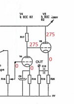
OK, you're drawing no current, so you're miswired at the tube. There ought to be 3V or so at the first cathode, 120V or so on the first plate and the second cathode.
This is so embarrassing...
Kevinkr's post got me thinking...and checking...and it turns out I had swapped cathode and anode connections for every single tube...
In hindsight this also explains why my power supply ended up being radically different to what I was expecting after my PSU designer modelling...there was hardly any current being drawn so ended up using huge resistors to get <300v. In hindsight, I should have suspected something was wrong!
Fixed it and switched it on. Of course now B+ has gone down to 50-60V so I'll need to play around with resistance values. Will have to wait till tomorrow - my girlfriend was not impressed last time she woke up and saw I was still on it...
Thanks a lot for the tips.
Best,
Nikos
it works!
Got the pre-amp to work this afternoon! I'm so excited! First piece I ever make from scratch! 😀
Left channel is very low in phono, as I seem to have damaged the resistor that feeds the anode of the left side of the first valve, but the right channel sounds very nice. Haven't tried the line stage with anything but test sounds yet so not sure what that's like.
Would be interested to hear some views on how I could tweak this in the future to optimise, but I'll start a separate thread on this.
Thanks!
Nikos 🙂
well done Nikos.
We all learn from embarrassing mistakes. incorrectly wired pins etc...
It's a learning curve and addictive.
Now I'm testing my first OTL - circlotron amp😀😀😀
Started with an Aikido, then many designs of headphone/preamps and now an OTL . yehhhh
You'll learn a lot from this forum if you continue.
We all learn from embarrassing mistakes. incorrectly wired pins etc...
It's a learning curve and addictive.
Now I'm testing my first OTL - circlotron amp😀😀😀
Started with an Aikido, then many designs of headphone/preamps and now an OTL . yehhhh
You'll learn a lot from this forum if you continue.
Unless the circuit has serious design errors it might be best to get used to it before tweaking, unless you built it to listen to audio rather than music.
I am so paranoid about getting things reversed that the number of time I check practically qualifies as a treatable psychiatric condition.
Kevinkr's post got me thinking...and checking...and it turns out I had swapped cathode and anode connections for every single tube...
That picture of yours with voltages showing should have been a dead giveaway for you.
You just can't get cathode follower to let through zero current with Vg equalling Va in normal operation - no way. Since your tube has been checked previously and confirmed to be OK that can only mean that tube is not conducting and about the only way to get a good tube in a correctly built circuit to not conduct is by reversing it 🙂
Description of the issue sounded just like swapped pins which is why I made that suggestion - I'm glad it that it was not something more insidious, but as I have done this myself more than once (and very recently if you check my 6V6 amp thread) I just had to mention it.. 😀 Glad it all turned out well..
Another quick question if I may; I'll be rebuilding this onto something a bit more permanent soon (currently lives on a turret board without chassis), adding a few bells and whistles (input selector, tape output and some other bits and bobs) so I was wondering if there are any component considerations to make. Was originally planning to re-use most capacitors (as they were not exactly cheap - polystyrene for all non-electrolytics in the phono section and polyester elsewhere) and whatever resistors I can be bothered to salvage.
Would you recommend I go down the route of higher-end components or is it a waste of money and effort? Which part of the design would you spend a bit money on and how much difference could I make? Any specific hints or suggestions?
Please note that I cannot afford any of the $20-30 per cap stuff. $5-10 per component for a couple that would make a clear difference and $4-5 a pop for a few more would be fine, but the most I could really spend in total would be $70-$80 (£50) and this only if people think it's worth it.
Thanks,
Nikos
I'd optimize tubes and operating points- FAR more important than components (assuming you've got decent but non-fancy components).
- Status
- Not open for further replies.
- Home
- Amplifiers
- Tubes / Valves
- Help - the pre amp I made is not working!