I'd optimize tubes and operating points- FAR more important than components (assuming you've got decent but non-fancy components).
Absolutely correct on the components front - didn't cut any corners but nothing exotic.
On the tubes front I think I'm ok, they are all special edition ECC80X and spent quite a bit of money on them.
By operating points, are you referring to the power supply? Considering moving to regulated B+ for the finished project, any suggestions? Would like to avoid tubes in the power supply - will be external and want to be able to hide it behind the record players stand without worrying if it will break. (Ultimately this will be a double phono pre-amp which is summed before the line stage to allow for rudimentary cross-fading of two sources, in other words a fancy DJ mixer without all the features I seldom use at home.)
Thanks,
Nikos
Last edited:
Well, you can buy a fancy ECC82 but... it's still an ECC82. That is not a particularly linear tube. So you might think about changing that to something different, the tube choice depending on the gain you actually need. It's possible (especially if all of your sources are things like CD players) that you don't even need gain in your linestage, in which case, you can convert it to a unity gain buffer. If you go that route, you definitely want to consider a higher transconductance tube than the ECC82.
By "operating point," I mean the plate voltage, plate load, and plate current (which by default encompasses grid bias as well).
By "operating point," I mean the plate voltage, plate load, and plate current (which by default encompasses grid bias as well).
A possible alternative for the ECC82 is the ECC804, also known as 6/30L2. This is quite cheap in UK/Europe, but appears to be the same valve as the 'Mazda 6CG7' sold in the US. Don't pay extra for a 'Mullard' one, as all the ones I have seen in the UK were made by Brimar/Mazda/STC whatever brand they are. The heater is different from ECC82: pins 4 and 5 (6.3V 300mA - no 12.6V option), pin 9 is a screen (same pinout as ECC88). As SY says, if you decide to go for a cathode follower instead then you need a higher gm.
Well, you can buy a fancy ECC82 but... it's still an ECC82. That is not a particularly linear tube. So you might think about changing that to something different, the tube choice depending on the gain you actually need. It's possible (especially if all of your sources are things like CD players) that you don't even need gain in your linestage, in which case, you can convert it to a unity gain buffer. If you go that route, you definitely want to consider a higher transconductance tube than the ECC82.
By "operating point," I mean the plate voltage, plate load, and plate current (which by default encompasses grid bias as well).
It's true that I don't need anywhere near as much gain as this has and was considering adding feedback to take it down a bit. Was in fact thinking about using a variable resistor in the loop, adding another "level" of volume control which I can vary depending on what this goes into.
Could you point me to somewhere where I could read about unity gain buffers and/or recommend a circuit? What valve(s) did you have in mind?
Having read around forums and sites, noticed suggestions that swapping the ECC82 with a 12BH7 offers improvement - any experiences? Perhaps another option is to change it for an ECC81? That's supposed to be less noisy, right?
ECC81 would not be my choice here, a previous suggestion to use a 6CG7 was an excellent one. This device has linearity to match the 6SN7 - far better than either the ECC82 or '81. The 12BH7 in most instances is an improvement over the ECC82, but the 6CG7 is better still.
ECC81 is fine for use as a cathode follower, or as a low-noise input, but it has far too much gain for a line stage. It is not particularly linear, except when used with small signals, as it was designed to be a VHF amplifier/mixer.
Could you point me to somewhere where I could read about unity gain buffers and/or recommend a circuit? What valve(s) did you have in mind?
This is the preamp I use (I just built a new version for use with a DCX2496):
SYclotron Audio The Heretical Preamp
ECC88 is a fine tube for cathode follower (unity gain) service, though an ECC81 will work adequately in most setups. I have a rare disagreement with DF96 regarding ECC81 distortion levels, but that's moot here- like most setups, you just don't really need much (if any) linestage gain.
One warning: there's a psychological issue with unity gain stages- it somehow "feels" wrong that the volume control has to be run so high, so it's easy to imagine that you're somehow "losing" dynamics. In reality, not only are dynamics preserved, but running the control at its upper ranges means that channel-to-channel tracking is often better.
One warning: there's a psychological issue with unity gain stages- it somehow "feels" wrong that the volume control has to be run so high, so it's easy to imagine that you're somehow "losing" dynamics. In reality, not only are dynamics preserved, but running the control at its upper ranges means that channel-to-channel tracking is often better.
I actually want to run the volume pot high as it is a mixer I am making ultimately and to cross-fade effectively I need to have enough "steps" between zero sound and "normal" volume levels.
I am also feeding it into an integrated stock Rogers Cadet III, with ECC807s in its line stage (these have heaps of gain) and this driving very high efficiency speakers. So, current gain levels are an annoyance, as it means I have to keep both (pre-amp and rogers)volume pots at 10% to avoid becoming deaf and/or being dumped by my girlfriend. In retrospect I should have built it with feedback from the beginning but as I'm using fairly low output cartridges (they are high output MCs but lower than most MM) I wanted to try it out first.
Thanks for the link - it is a bit more than I'm prepared to do for this project. May try to use the design with a pentode phono stage I was considering trying out at some point.
The Red Light District was what caught my attention most - great read from a purely educational point of view and nice project!
Last edited:
ECC81 would not be my choice here, a previous suggestion to use a 6CG7 was an excellent one. This device has linearity to match the 6SN7 - far better than either the ECC82 or '81. The 12BH7 in most instances is an improvement over the ECC82, but the 6CG7 is better still.
I guess I could re-do the heaters supply to 6.3V and try the 6CG7. My only fear is that I'm not sure my transformer will be able to handle the higher current draw - I will need to supply 8 tubes in the finished product and doubt it can do 5A. There are two pairs of 6.3V taps. From a current draw point of view, can I treat them as two separate sources?
I guess I could re-do the heaters supply to 6.3V and try the 6CG7. My only fear is that I'm not sure my transformer will be able to handle the higher current draw - I will need to supply 8 tubes in the finished product and doubt it can do 5A. There are two pairs of 6.3V taps. From a current draw point of view, can I treat them as two separate sources?
What is the rating of each tap? One option would be to just place the 6CG7 filaments (channel to channel) in series.. I am not sure where your filament current numbers are coming from as there are 5 stages per channel so even with the 6CG7 I come up with only 900mA - 975mA per channel or < 2A total on 6.3V, it would be half this on 12.6V.. 12AX7 per envelope (2 triodes) use 300mA at 6.3V and 150mA at 12.6V, the 5751 uses 350mA/175mA respectively, and the 6CG7 is 600mA @ 6.3V per envelope two in series on 12.6V would be 600mA.. I'd just use one winding per channel assuming that they are rated at >1A or are you using dc heating in which case the numbers are a bit worse and I'd recommend 12.6V for better efficiency. (rectifier and winding losses, regulator drop-out voltage, etc.)
Last edited:
What is the rating of each tap? One option would be to just place the 6CG7 filaments (channel to channel) in series.. I am not sure where your filament current numbers are coming from as there are 5 stages per channel so even with the 6CG7 I come up with only 900mA - 975mA per channel or < 2A total on 6.3V, it would be half this on 12.6V.. 12AX7 per envelope (2 triodes) use 300mA at 6.3V and 150mA at 12.6V, the 5751 uses 350mA/175mA respectively, and the 6CG7 is 600mA @ 6.3V per envelope two in series on 12.6V would be 600mA.. I'd just use one winding per channel assuming that they are rated at >1A or are you using dc heating in which case the numbers are a bit worse and I'd recommend 12.6V for better efficiency. (rectifier and winding losses, regulator drop-out voltage, etc.)
Sorry - misread my notes and thought that the ECC83 and 81 drew as much as the 6CG7.
Still, it is more than 2A:
By mixer I mean that I will have two times the circuit up to the volume pot and this fed into the line stage and cathode follower using resistors (with the addition of feedback which, according to the research I have done, improves isolation and distortion and reduces gain).
So, will have to supply four ECC83s (.3A @ 6.3V), three ECC81s (the two volume stages and the final cathode follower - .3A @6.3V) and one 6CG7 or whatever I have there (up to .6A @ 6.3V). Total of 2.7 if using the 6CG7
Total would be approximately 2.7A. I have no idea what the rating of the heaters taps on my transformer is - I salvaged it from an old valve amp I picked up on ebay. This is part of the reason I went for 12.6V to begin with. Currently running a regulated DC supply.
When you say "place the 6CG7 filaments (channel to channel) in series", presume you mean "pin 4 of valve A connected to pin 5 of valve B and live and neutral connected to the other two heater pins". As I am only using one 6CG7, I guess I could instead connect one of its pins to the heaters centre tap of the cathode follower and then my live and neutral to the remaining pin of the 6CG7 and the two heater connections of the cathode follower (so that it also draws 6.3V). Do you think this would work? It's easy enough to do and I could try what each of these combinations sound.
Can I just leave the rest of the design the same if I try the 6CG7?
Alternatively, would just using a resistor in series or a voltage divider to drop the ~12V of my supply to ~6V for the specific valve be ok? Any noise implications? Would wirewound be the way to go to minimise the latter?
You could drop heater voltage with a resistor, but this wastes power. Better if possible to drop with another heater. No noise implications, as resistor noise is way lower than the 6V hum which valves are designed to cope with.
You could drop heater voltage with a resistor, but this wastes power. Better if possible to drop with another heater. No noise implications, as resistor noise is way lower than the 6V hum which valves are designed to cope with.
The ECC81 (cathode follower) draws 300mA @ 6.3V whereas the 6CG7 600mA, is it still ok to hook up the former's two heaters in parallel (using the centre tap) with the latter in series and supply 12V you think? Would both valves fillaments get 6.3V or could there be an imbalance?
Most importantly, do you know what tolerances fillaments have? Can I afford to just try it and see, or would I bugger them up if one got, say 7-8V or something and the other the balance?
thx
Another quick question if I may; I'll be rebuilding this onto something a bit more permanent soon (currently lives on a turret board without chassis), adding a few bells and whistles (input selector, tape output and some other bits and bobs) so I was wondering if there are any component considerations to make. Was originally planning to re-use most capacitors (as they were not exactly cheap - polystyrene for all non-electrolytics in the phono section and polyester elsewhere) and whatever resistors I can be bothered to salvage.
Would you recommend I go down the route of higher-end components or is it a waste of money and effort? Which part of the design would you spend a bit money on and how much difference could I make? Any specific hints or suggestions?
Please note that I cannot afford any of the $20-30 per cap stuff. $5-10 per component for a couple that would make a clear difference and $4-5 a pop for a few more would be fine, but the most I could really spend in total would be $70-$80 (£50) and this only if people think it's worth it.
Thanks,
Nikos
In the arena of affordable and nice sounding parts are IRC RN60 "metal glaze" resistors, only about $0.35 each from Handmade Electronics in Allentown, PA, US. For nice and affordable caps, Sonicap Gen I, Wima FKP (not the metalized ones), and Multicap PPFX (not the PPMFX) are excellent values. For wire, Handmade also sells a Belden 8C 24 AWG cable (1701LC) with Teflon insulation over copper (not silver plated). For $1.35 a foot of cable, you get 8' of Teflon insulated copper 24 gauge wire.
Hope this helps. Not sure about pricing overseas.
Stuart
If you put valve heaters in series then they must have the same current rating, so you can't put a 300mA in series with a 600mA. If you do the 300mA one will get much too hot and the 600mA hardly warm at all. You can put a 600mA in series with (two 300mA in parallel).
You could try the 6/30L2 (ECC804). This has a 300mA heater, but 6CG7-like characteristics (apart from the maximum anode dissipation being lower).
PS my personal view is that expensive boutique components will enhance the placebo effect and make your system sound much better.
You could try the 6/30L2 (ECC804). This has a 300mA heater, but 6CG7-like characteristics (apart from the maximum anode dissipation being lower).
PS my personal view is that expensive boutique components will enhance the placebo effect and make your system sound much better.
Last edited:
PS my personal view is that expensive boutique components will enhance the placebo effect and make your system sound much better.
😀
The nice thing about DIY is you get to choose your own recipe. If you know that expensive parts are a waste of time foisted on stupid audiophiles with more money than sense, then you're the winner. You save lots of time and money, not needing to experiment and listen to different components and pick the best mix. You knew best before you even started. Why even ask anyone else, when you knew there is no difference? Just idiots wasting their money. But you're too smart to be fooled by them!😉
If you put valve heaters in series then they must have the same current rating, so you can't put a 300mA in series with a 600mA. If you do the 300mA one will get much too hot and the 600mA hardly warm at all. You can put a 600mA in series with (two 300mA in parallel).
and you'll see it glow much brighter! don't ask me how I know!!!🙄🙄
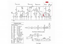
Could I please ask for some more help? I've been experimenting with adding feedback to reduce gain and I'm having a bit of a problem. I have attached the schematic with that I have added to it - a resistor the value of which I'm experimenting between the output and the grid of the line stage valve driver and another 100K resistor between the pot and that grid.
200K where the question marks are does reduce the volume, but nowhere near enough. 100K is better, but this adds a very disturbing repetitive "thump", almost like turning up the "feedback" control on an analogue delay/echo FX unit. Without really understanding these principles deeply (I promise I will one day read Morgan Jones' book!), I suspect this means that rather than negative I am having positive feedback? Am I right? Why is this happening?
And the million dollar question: can anyone guess/calculate what value resistance I need to reduce gain to unity (or thereabouts) and explain how they did it? Also, is it possible to add a variable resistor there, to tweak the overall gain of the line stage?
Thanks,
Nikos
PS this is all a separate issue to the earlier discussions about changing valves used - I will probably do this anyway, but for the time being I want to understand how feedback works and how to tweak its parameters.
Attachments
Last edited:
- Status
- Not open for further replies.
- Home
- Amplifiers
- Tubes / Valves
- Help - the pre amp I made is not working!