Could the issue have anything to do with the fact that originally there was also a brown wire that came from the OS to the board ? There isn’t anywhere for this wire on the new board so I was told to discard it .

Yes Zen , voltage is variable when adjusting pot p2 but no voltage at resistorvoltage between D+ and D- is?
and - is it variable, while fiddling with trimpot?
that test possible even without OS connected to D+ and D-
in between those points is biasing generator for OS bases
I can't tell if the wiring is really correct to the output stage there. If this amp was in front of me I would need to go through the learning curve of identifying the parts to verify with absolute certainty that +C -C +D -D from the front end really go where they are supposed to. With that confirmed, I would be looking for current flowing through the string of components in this first stage on the output board.
Attachments
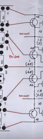

The one thing I’m not 100% confident with is if I have the OS resistors in their correct position
Being totally honest I can’t understand the drawing ( I’ve tried believe me )I can't tell if the wiring is really correct to the output stage there. If this amp was in front of me I would need to go through the learning curve of identifying the parts to verify with absolute certainty that +C -C +D -D from the front end really go where they are supposed to. With that confirmed, I would be looking for current flowing through the string of components in this first stage on the output board.
Just checked Gary’s drawing again that he made for me and all wiring and resistors are correct so I’ve totally hit a wall with this 😩

In the picture you posted #286, top row of resistors, 2nd & 3rd from RIGHT, is that a solder bridge going between them across the blue box line? I can't be sure because photo is a bit fuzzy on magnification.
Not sure we're looking at the right bit. Stupidly my first stab at a post I said left and meant right 🙁

I just gave it another go on the P2 and I’m sure I can feel a little heat coming from the FE board and also that new component smell?
I’ve turned the pot back off again.
I’ve turned the pot back off again.
Yup, that's it. It looks like it's bridging to me.
Also, take a close look at the rightmost leg of the first resistor on the right. Probably not bridging there, but awfully close.
I'd be inclined to clear that bit of solder on the blue line at the lh end of resistor 3. It's probably loose and could end up anywhere anytime...
Also, take a close look at the rightmost leg of the first resistor on the right. Probably not bridging there, but awfully close.
I'd be inclined to clear that bit of solder on the blue line at the lh end of resistor 3. It's probably loose and could end up anywhere anytime...
For heavens sake do check continuity before powering up, work slow work in stages , dont look at the complete amp divide it up ,check each section, wing it off, next...
Well spotted, it was a bit of solder that I’ve now blown off . I’ll check out that 3rd resistor, cheers.Yup, that's it. It looks like it's bridging to me.
Also, take a close look at the rightmost leg of the first resistor on the right. Probably not bridging there, but awfully close.
I'd be inclined to clear that bit of solder on the blue line at the lh end of resistor 3. It's probably loose and could end up anywhere anytime...
Continuing was checked over and over before start up last week, without continuity it wouldn’t have got this far 😁for heavens sakeFor heavens sake do check continuity before powering up, work slow work in stages , dont look at the complete amp divide it up ,check each section, wing it off, next...
One thing, looking at the photo I've attached is that resistor correct? It seems to be different to the others, top leg soldered in correct place?
Take a look at both of those output doobries. From the photos I can still see what appear to be bridges across those blue lines.
Give them another going over with a MK1 eyeball. I follow gaps between tracks/pads with a cocktail stick and magnifying glass to keep my focus in one place, or take a sharp photo and zoom in then slowly scroll...
You are close to getting this thing working, don't leave any turn unstoned.
- Home
- Amplifiers
- Pass Labs
- Help please with my poorly Stasis 2